39
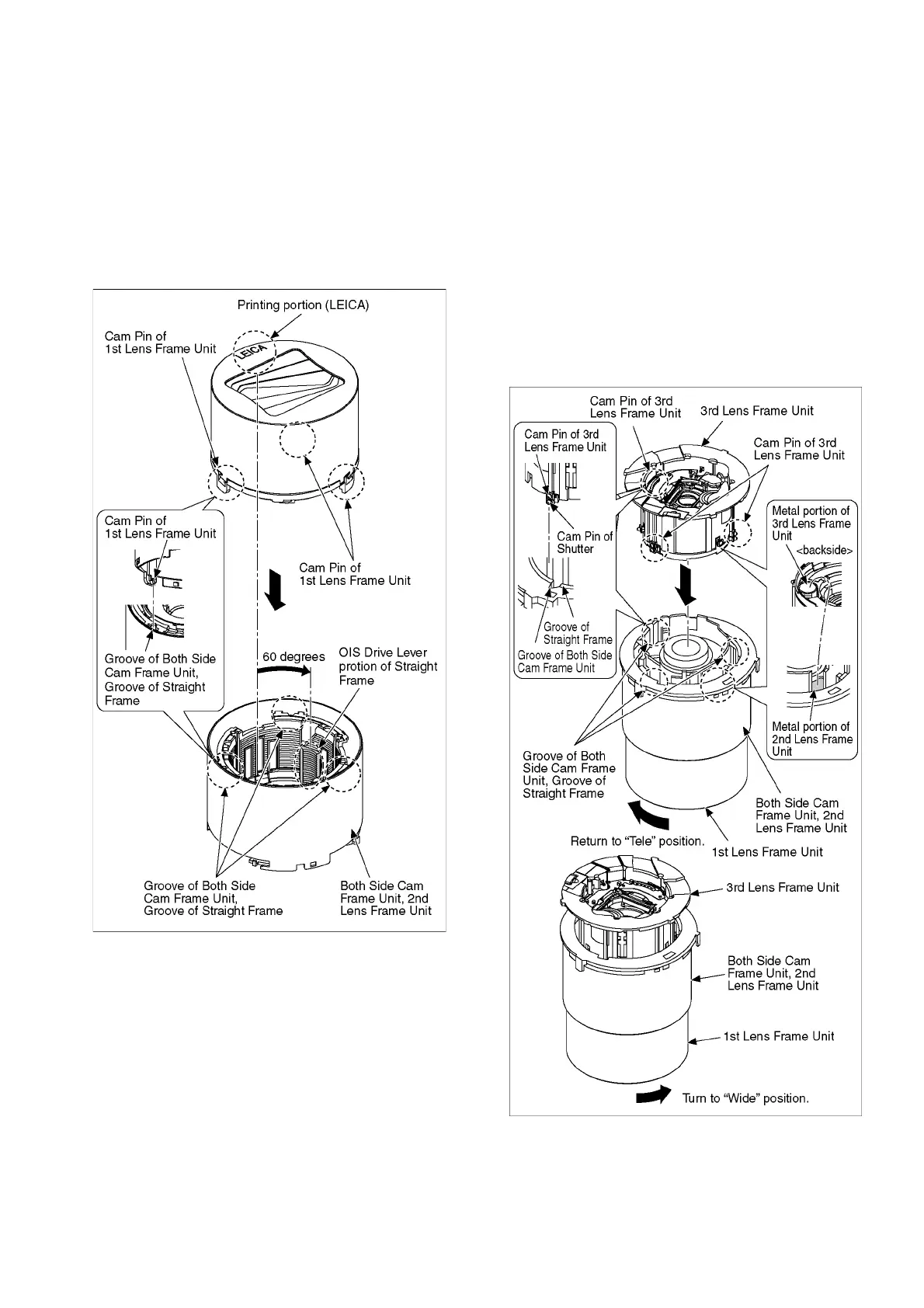
2. Insert the 1st Lens Frame Unit as the drawing below
indicated.
(1) Position the printing portion (LEICA) of the 1st Lens
Frame Unit and the OIS Drive Lever portion of the
Both Side Cam Frame Unit as shown below.
(deviated approx. 60 degrees)
(2) Insert the each Cam Pin of the 1st Lens Frame Unit in
the each Groove of the Both Side Cam Frame Unit
and the Straight Frame.
* Check if the 2nd Lens Frame Unit moves smoothly
when the 1st Lens Frame Unit is rotated.
9.5.3. Insert the 3rd Lens Frame Unit
1. Insert the 3rd Lens Frame Unit as the drawing below
indicated.
(1) Restore the position to the state ("Tele" position) when
the 1st Lens Frame Unit is inserted.
(Align the each Groove of the Straight Frame and the
each Groove of the both Side Cam Frame Unit.)
(2) Align the metal part of the 3rd Lens Frame Unit with
the metal part of the 2nd Lens Frame Unit.
(3) Insert the each Cam Pin of the 3rd Lens Frame Unit
and Shutter Cam Pin in the each Groove of the Both
Side Cam Frame Unit and the Straight Frame.
2. Make the lens into a retracted position state. ("Wide"
position)
(Turn the 1st Lens Frame Unit and 3rd Lens Frame Unit in
the direction of arrow fully.)
 Loading...