7
3 Service Navigation
3.1. Introduction
This service manual contains technical information, which will allow service personnel's to understand and service this model.
Please place orders using the parts list and not the drawing reference numbers.
If the circuit is changed or modified, the information will be followed by service manual to be controlled with original service manual.
3.2. Important Notice
3.2.1. About lens block
The image sensor (MOS) unit which are connected to the lens unit with 3 screws. These screws are locked, after performing the
Optical tilt adjustment. During servicing, if one of MOS fixing screws are loosened, the Optical tilt adjustment must be performed.
(About the Optical tilt adjustment, refer to the "10.3.2 Adjustment Specifications" for details.)
• Using the Extension cable, perform the Optical tilt adjustment according to the following procedure.
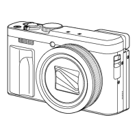
1. Remove the Frame Plate. (Refer to Disassembly
Procedures.)
2. Remove the Speaker from the Frame.
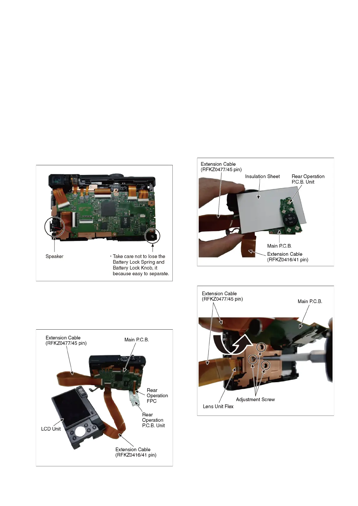
3. Using the Rear Operation FPC, connect the Main
P.C.B. to Rear Operation P.C.B. Unit.
4. Using the Extension cable, connect the Main P.C.B. to
LCD Unit.
5. Using the Extension cable, connect the Main P.C.B. to
Lens Unit Flex.
6. Insulation Sheet is inserted between the Rear
Operation P.C.B. Unit and the Main P.C.B.
7. The Main P.C.B. is lifted, perform the Optical tilt
adjustment.
 Loading...