Mini VRF SYSTEM
Remote Controller Functions
5 - 13
2. Detailed Settings Function
5
2. Detailed Settings Function
List of Detailed Setting Items
Item code
Item
.oN.oN.oN
Setting data
Description DescriptionDescription
0001Type
Indoor unit
capacity
0003
0009
0012
0017
0001 Unit No. 1
0002 Unit No. 2
0003 Unit No. 3
0030 Unit No. 30
System
address
0099 Not set
0001 Unit No. 1
0002 Unit No. 2
0003 Unit No. 3
0064 Unit No. 64
Indoor unit
address
0099 Not set
0000 Individual (1:1 = Indoor unit with no group wiring)
0001 Main unit (One of the group-control indoor units)
0002 Sub unit (All group-control indoor units except for main unit)
Group control
address
0099 Not set
010
Shifts intake temperature 10°C down.
009
Shifts intake temperature 9°C down.
001
Shifts intake temperature 1°C down.
0000 No intake temperature shift
0001
Shifts intake temperature 1°C up.
0009
Shifts intake temperature 9°C up.
Cooling
intake
temperature
shift
0010
Shifts intake temperature 10°C up.
0000 Function disabled
0001 Stops automatically 5 minutes after operation starts.
0002 Stops automatically 10 minutes after operation starts.
0123 Stops automatically 615 minutes after operation starts.
0124 Stops automatically 620 minutes after operation starts.
Automatic
stop time
after
operation
start
*Can be set
in 5-minute
units.
0125 Stops automatically 625 minutes after operation starts.
0005
0038
0008 Wall Mounted (K2)
15 (Type 15)
0001
0007
0015
4-Way Cassette (60×60) (U2, Y2)
Slim Low Static Ducted (M1)
0010
0018
0005
001363 (Type 60)
36 (Type 36)
160 (Type 160)
90 (Type 90)
112 (Type 106)
22 (Type 22)
45 (Type 45)
28 (Type 28)
56 (Type 56)
80 (Type 73)
140 (Type 140)
2WAY SYSTEM
Remote Controller Functions
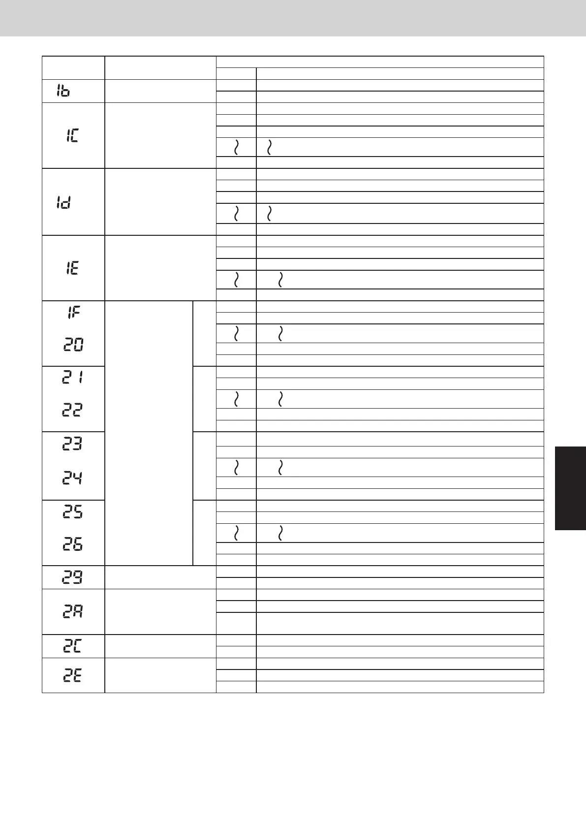
Item code Item
Setting data
No. Description
(1B) Forced thermostat ON time
0000 5 minutes
0001 4 minutes
Cooling discharge
temperature shift
–010 Shifts discharge temperature setting 10°C down
–009 Shifts discharge temperature setting 9°C down
–008 Shifts discharge temperature setting 8°C down
0010 Shifts discharge temperature setting 10°C up
(1D)
Heating discharge
temperature shift
–010 Shifts discharge temperature setting 10°C down
–009 Shifts discharge temperature setting 9°C down
–008 Shifts discharge temperature setting 8°C down
0010 Shifts discharge temperature setting 10°C up
Temperature shift for
cooling/heating change in
auto heat/cool mode
0001 ±1°C
0002 ±2°C
0003 ±3°C
0007 ±7°C
(Upper limit)
Change to remote
control temperature
setting range
Cooling
0018 18°C (Lower limit at shipment)
0019 19°C
(Lower limit)
0029 29°C
0030 30°C (Upper limit at shipment)
(Upper limit)
Heating
0016 16°C (Lower limit at shipment)
0017 17°C
(Lower limit)
0029 29°C
0030 30°C (Upper limit at shipment)
(Upper limit)
Drying
0018 18°C (Lower limit at shipment)
0019 19°C
(Lower limit)
0029 29°C
0030 30°C (Upper limit at shipment)
(Upper limit)
Auto heat/cool
0017 17°C (Lower limit at shipment)
0018 18°C
(Lower limit)
0026 26°C
0027 27°C (Upper limit at shipment)
Humidifier operation
0000 Normal
0001 Ignore heat exchanger temperature conditions.
Filter (CN70) input
switching
0000 Filter input (differential pressure switch input)
0001 Alarm input (for trouble input about air cleaner or similar device)
0002
Humidifier input (Operates linked with drain pump when humidifier is
ON.)
Indoor unit electronic
control valve
0000 Present (Setting at shipment)
0002 None
T10 terminal switching
0000 Normal (Used as optional relay PCB or JEMA standard HA terminal.)
0001 Used for OFF reminder
0002 Fire prevention input
SM830289-01_欧州向け R32 mini VRF 8,10HP SM&TRSM.indb 13SM830289-01_欧州向け R32 mini VRF 8,10HP SM&TRSM.indb 13 2021/05/07 10:16:172021/05/07 10:16:17
 Loading...


