Mini VRF SYSTEM
Remote Controller Functions
5 - 14
2. Detailed Settings Function
5
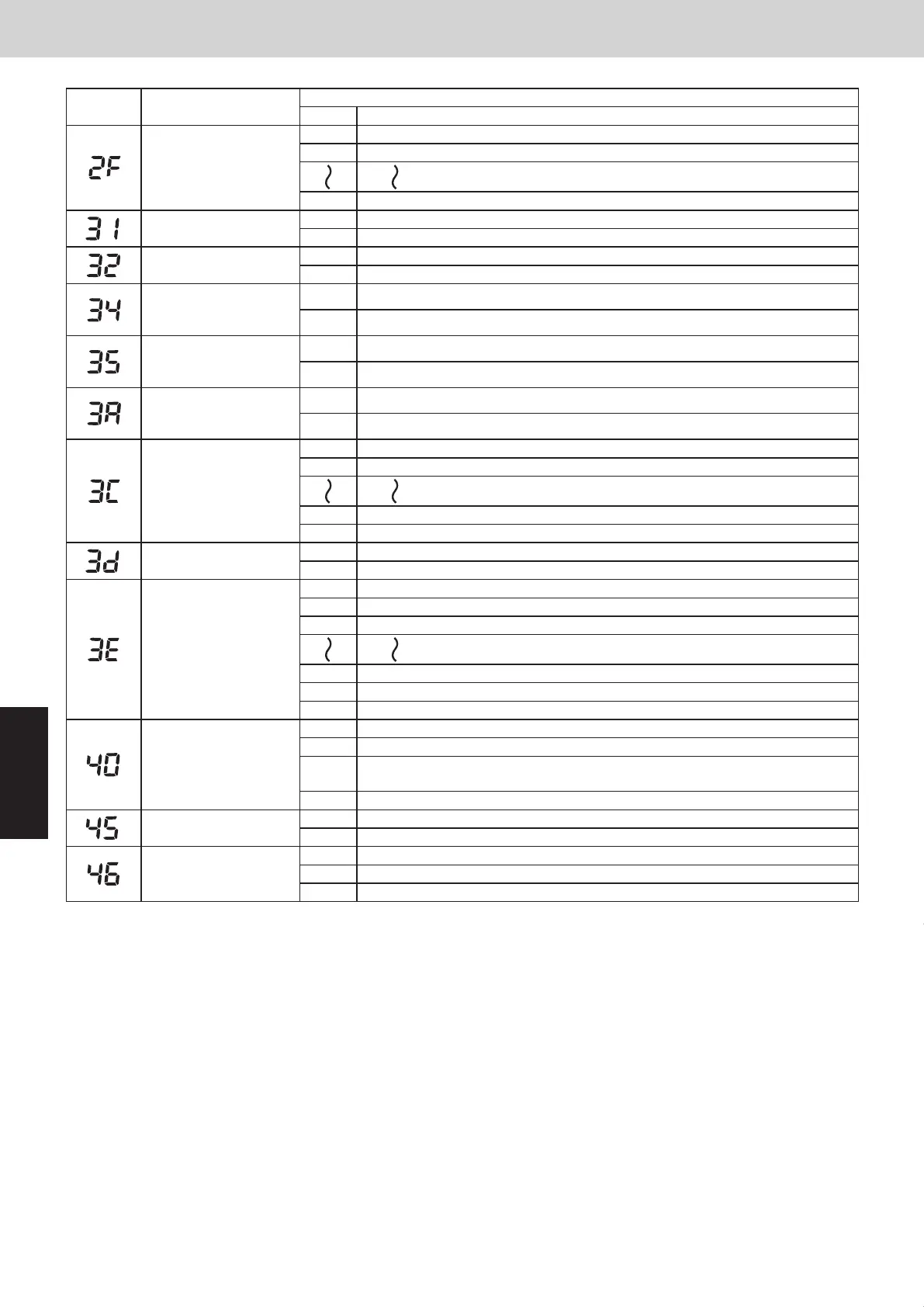
Item code Item
Setting data
No. Description
Automatic drain pump
operation
0000 No forced operation
0001 Forced operation for 1 minute
0060 Continuous operation
Ventilation fan operation
0000 None
0001 Ventilation fan operated by remote controller.
Wired remote controller
sensor
0000 Not used. (Body sensor is used.)
0001 Remote control sensor is used.
“Operation change
control in progress”
display
0000 Normal (displayed)
0001 Not displayed
OFF reminder function
for when weekly timer is
used
0000 None
0001 Only stop time setting is enabled.
Discharge temperature
control
0000 Discharge temperature control OFF
0001 Discharge temperature control ON
Heat exchanger
temperature for cold air
discharge
(Heat exchanger control
point for control to
prevent cold air)
0013 Control temperature 13°C
0014 Control temperature 14°C
0025 Control temperature 25°C
0026 Control temperature 26°C
Fan output switching
0000 Output linked with fan. (ON when indoor unit fan is operating.)
0001 Fan mode operation output
Drain pump delayed
stop time
0000 No delayed start
0001 1 minute delayed stop
0002 2 minutes delayed stop
0058 58 minutes delayed stop
0059 59 minutes delayed stop
0060 60 minutes delayed stop
Humidifier setting
0000 Humidifier output OFF. Drain pump stopped.
0001 Humidifier output ON. Drain pump operates.
0002
Humidifier output ON. Drain pump operates for 1 minute when total humidifier
operating time reaches 60 minutes.
0003 Humidifier output ON. Drain pump stopped.
Flap operation mode
0000 Standard setting
0001 Draft reduction mode (Flap lower-limit position is shifted upwards.)
Flap swing mode
0000 Smudging reduction mode (Flap swing upper-limit position is shifted downwards.)
0001 Normal mode
0002 Draft reduction mode (Flap swing lower-limit position is upwards.)
2. Detailed Settings Function
VRF SYSTEMS Indoor Unit
Item code Item
Setting data
No. Description
Fan tap setting
(Fan tap change in order
to prevent drop in air
discharge caused by
filter installation)
Purpose
0000 Standard (setting at shipment)
0001
High ceiling setting 1 (Type U2)
Air-flow blocking kit (when a duct is connected : Type U2)
Air-flow blocking kit (for 3-way airflow : Type U2)
0003
High ceiling setting 2 (Type U2)
0006
Air-flow blocking kit (for 2-way airflow : Type U2)
Humidifier ON time
(ON time per 60
seconds)
0000 No humidifier output
0001 1 second
0002 2 seconds
0058 58 seconds
0059 59 seconds
0060 Continuously ON
Timer function change
prohibit
0000 Function disabled
0001 Function enabled
Smudging control 0000 No smudging control
Waiting time for
dew condensation
prevention control
0000 Without dew condensation prevention control
0001 Dew condensation prevention control after 10 minutes
0002 Dew condensation prevention control after 20 minutes
0010 Dew condensation prevention control after 100 minutes
0011 Dew condensation prevention control after 110 minutes
0012 Dew condensation prevention control after 120 minutes
Setting the Flap
Separately
*Only for 4-Way
Cassette type
0000
0001
0002
0003
0004
0005
0006
Setting the Flap
Separately
*Only for 4-Way
Cassette type
Setting the Flap
Separately
*Only for 4-Way
Cassette type
Setting the Flap
Separately
*Only for 4-Way
Cassette type
Flap position
1
2
3
4
5
Flap position during operationSetting data
Move to position 1 and stay
Without separate setting
Swing
Move to position 2 and stay
Move to position 3 and stay
Move to position 4 and stay
Move to position 5 and stay
When the flap position is set to
4 or 5 and the unit is in the
cooling or dry mode, the flap
position is moved to 3 and the
operation is started.
The flap swings during the
operation under "Setting the
Flap Separately".
At this time, the unselected flaps
are moved to the position 1 .
NOTE
Air outlet flap
(adjustment for up-down
airflow direction)
=91
(Motor No. 4)
(Motor No. 1)
(Motor No. 2) (Motor No. 3)
Flap 3
Flap 2Flap 4
=92
=93
Electrical
component
box
SM830232-03_欧州向けVRF Indoor SM&TRSM.indb 18 17/06/27 20:21:51
SM830289-01_欧州向け R32 mini VRF 8,10HP SM&TRSM.indb 14SM830289-01_欧州向け R32 mini VRF 8,10HP SM&TRSM.indb 14 2021/05/07 10:16:192021/05/07 10:16:19
 Loading...


