Mini VRF SYSTEM
Test Run
7 - 20
7
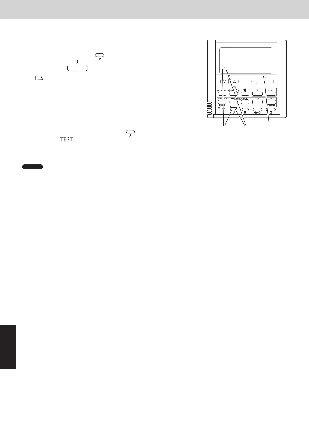
5. Test Run Using the Remote Controller
CZ-RTC4 (Timer remote controller)
This mode places a heavy load on the machines. Therefore use it only
when performing the test run.
(1) Press the remote controller
button for 4 seconds or longer.
Then press the
button.
“
” appears on the LCD display while the test run is in progress.
• The test run can be performed using the HEAT, COOL, or FAN
operation mode.
• The temperature cannot be adjusted when in test run mode.
• If correct operation is not possible, a code is displayed on
the remote controller LCD display. (See “7. Self-Diagnosis Function
Table and Contents of Alarm Display” and correct the problem.)
(2) After the test run is completed, press the
button again.
Check that “ ” disappears from the LCD display.
• To prevent continuous test run, this remote controller includes a timer function that cancels the test run after
60 minutes.
NOTE
• The outdoor units will not operate for approximately 3 minutes after the power is turned ON and after operation is
stopped.
6. Caution for Pump Down
Pump down means refrigerant gas in the system is returned to the outdoor unit.
Pump down is used when the unit is to be moved, or before servicing the refrigerant circuit.
This outdoor unit cannot collect more than the rated refrigerant amount as shown
by the nameplate on the back.
If the amount of refrigerant is more than that recommended, do not conduct pump
down.
In this case use another refrigerant collecting system.
7. Self-Diagnosis Function Table and Contents of Alarm Display
How to know LEDs 1 and 2 alarm display on outdoor unit control PCB
LED 1 LED 2 Contents of Alarm Display
Alarm display
After LED1 blinks M times, LED2 blinks N times.
This will be repeated.
Number of blinks Type of alarm
N = number of alarm No.
M
2 Alarm P
3 Alarm H
4 Alarm E
5 Alarm F
6 Alarm L
For example: After LED1 blinks twice, LED2 blinks 17 times. This will be repeated.
The alarm shows “P17”.
Alternately
(
: Blink) Connect the outdoor unit maintenance remote controller to the RC plug (3P, BLU) on outdoor unit control PCB
(Main) and make confirmation.
n
Self-Diagnosis Function Table
•• Cause and countermeasure against the symptom of auto address failure
Symptom Cause and countermeasure
•• When turning on power to the outdoor main unit, LEDs 1 and 2
illuminate or blink excluding going out.
Auto address setting is not available.
See “Contents of Alarm Display” and make corrections.
•• When auto address setting by the remote controller begins, the
alarm display appears immediately.
•• When auto address setting by the remote controller begins, no
display appears.
Are remote control wiring and inter-unit control wiring
connected properly?
Is indoor unit turned on power?
SM830289-01_欧州向け R32 mini VRF 8,10HP SM&TRSM.indb 20SM830289-01_欧州向け R32 mini VRF 8,10HP SM&TRSM.indb 20 2021/05/07 10:16:522021/05/07 10:16:52