Mini VRF SYSTEM
Test Run
7 - 25
7
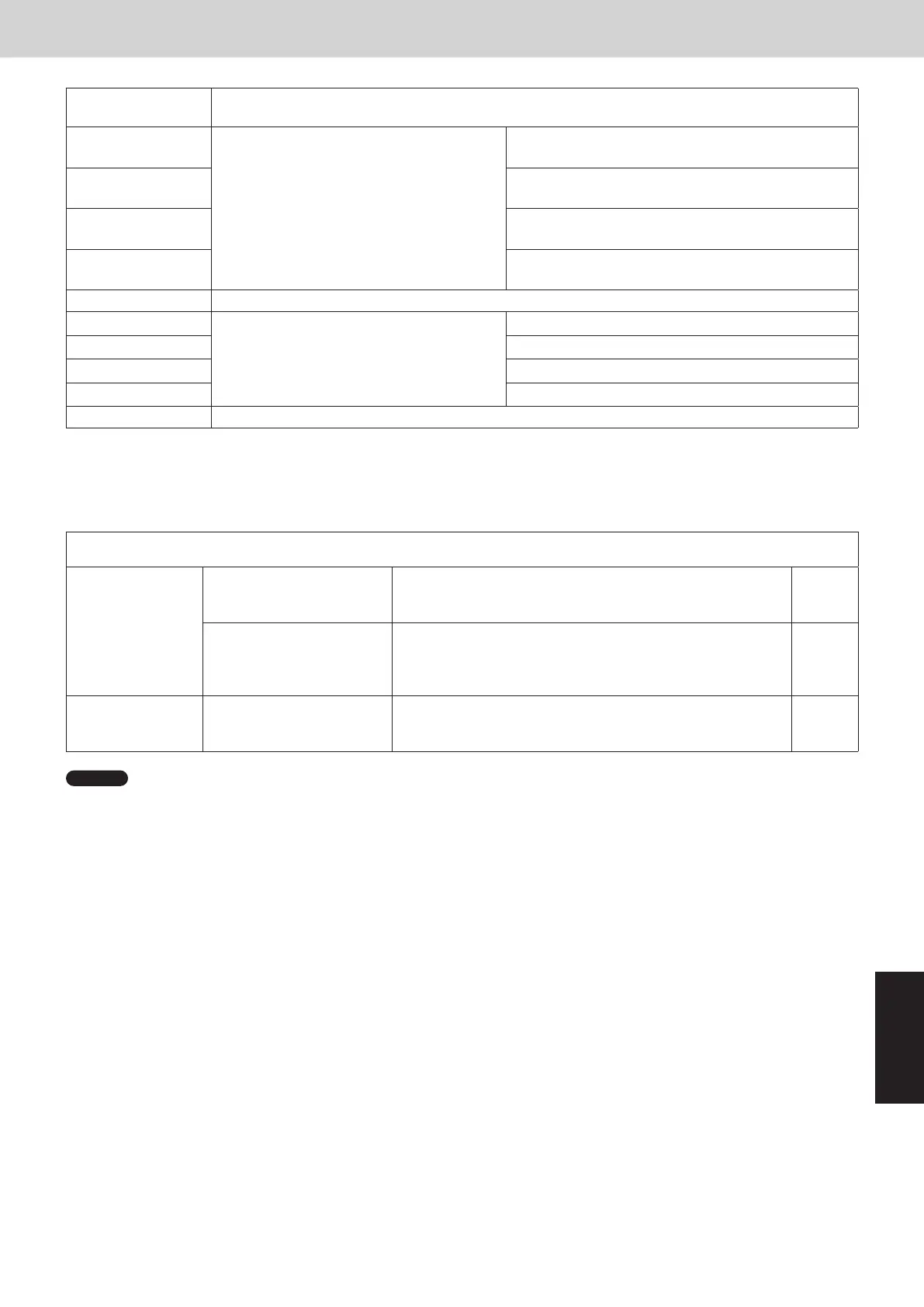
7. Self-Diagnosis Function Table and Contents of Alarm Display
Remote control display Alarm contents
L08 Indoor unit address is not set.
L09 Capacity setting of indoor unit is not correct.
L10 Capacity setting of outdoor unit is not correct.
L13 Indoor unit model does not match with outdoor unit.
L17 Model mismatch between outdoor units.
L18 4-way valve has failure.
P01 Thermal protector for Indoor unit fan motor is activated.
P03 Compressor discharge temperature is too high.
P04 High pressure switch is activated.
P05 AC power supply has abnormal.
P08
Refrigerant leakage detection of indoor unit connected with the remote controller displaying this
alarm.
P09 Connection to the panel of indoor unit is not good.
P10 Float switch of drain pan safety is activated.
P11 Drain pump failure or locked rotor.
P12 Indoor unit fan inverter protection control is activated.
P14 Refrigerant leakage detection of one of the indoor units connected to the outdoor unit.
P16 Compressor secondary current is overcurrent.
P20 Too high load in refrigerant circuit.
P22 Outdoor unit fan motor has failure.
P29 Compressor start failure. Compressor is missing phase or reverse phase.
P31 Other indoor unit in group control has an alarm.
•• Contents of alarm display on remote controller
For the remote controller, there are other alarm contents listed on the following table besides the alarm display
on outdoor unit control PCB (Main).
Wired remote
control display
Detected contents
<E01>
Remote controller is detecting error signal
from indoor unit.
Indoor unit does not respond to remote controller.
<E02>
Remote controller is having error in sending serial
communication signal.
<<E03>> Remote controller does not respond to indoor unit.
E04
Remote controller is detecting error signal
from outdoor unit.
Outdoor unit does not respond to indoor unit.
E08
Improper setting
Indoor unit address is duplicating.
<<E09>>
Two or more remote controllers are set as main on
R1-R2 link.
E18
Indoor unit communication error in group
control wiring
No response from sub indoor to the main indoor unit in
group control wiring.
<<L02>>
Improper setting
Indoor unit model does not match with the outdoor unit
model. (Multi-split/mini-split)
<L03>
Two or more indoor units are set as main in group
control.
L07
Group control wiring is detected for indoor unit set as
individual control.
L08
Indoor unit address is not set.
<<L09>>
Capacity setting of indoor unit is not correct.
Wired remote
control display
Detected contents
<<F01>>
Indoor unit sensor has failure
Indoor unit heat exchanger liquid temperature sensor
has failure. (E1)
<<F03>>
Indoor unit heat exchanger gas temperature sensor
has failure. (E3)
<<F10>>
Indoor suction air (room) temperature sensor has
failure. (TA)
<<F11>>
Indoor discharge air temperature sensor has failure.
(BL)
<<P09>> Connection to the panel of indoor unit is not good.
<<P01>>
Activation of protective device for Indoor unit
Thermal protector for Indoor unit fan motor is activated.
<<P10>>
Float switch of drain pan safety is activated.
<<P11>>
Drain pump failure or locked rotor.
<<P12>>
Indoor unit fan inverter protection control is activated.
F29 EEPROM on indoor unit control PCB has failure.
• The parentheses of << >> used in the table of alarm display does not affect anything the operation of other
indoor units.
• The parentheses of < > used in the table of alarm display implies that there are two cases : according to the
content of the symptom, some affect the operation of other indoor units and others do not affect anything.
Alarm messages displayed on system controller
Serial
communication
errors
Mis-setting
Error in transmitting serial
communication signal
Indoor or main outdoor unit is not operating correctly.
Mis-wiring of control wiring between indoor unit, main outdoor
unit and system controller.
C05
Error in receiving serial
communication signal
Indoor or main outdoor unit is not operating correctly.
Mis-wiring of control wiring between indoor unit, main outdoor
unit and system controller.
CN1 is not connected properly.
C06
Activation of
protective device
Protective device of sub
indoor unit in group control is
activated.
When using wireless remote controller or system controller,
in order to check the alarm message in detail, connect wired
remote controller to indoor unit temporarily.
P30
NOTE
1. Alarm messages in << >> do not affect other indoor unit operations.
2. Alarm messages in < > sometimes affect other indoor unit operations depending on the fault.
SM830289-01_欧州向け R32 mini VRF 8,10HP SM&TRSM.indb 25SM830289-01_欧州向け R32 mini VRF 8,10HP SM&TRSM.indb 25 2021/05/07 10:16:532021/05/07 10:16:53