Mini VRF SYSTEM
Test Run
7 - 26
7
7. Self-Diagnosis Function Table and Contents of Alarm Display
ATTENTION!
Adjustment of terminating resistance (pin) is necessary.
Communication failure will occur unless adjustment is made correctly.
• Terminating resistance (pin) is mounted on outdoor unit control PCB.
• When connecting central controller, interface or peripheral equipment, adjustment of terminating resistance
(pin) is necessary. Although the connection is not made, confirmation is necessary for VRF systems.
• In the case of a refrigerant system, the terminating resistance (pin) for this inter-unit control wiring (S-LINK
wiring) is one location (See “4. Auto Address Setting”).
For 2 or more refrigerant systems, 2 locations should be valid (SHORT for VRF systems at shipment). See
“4. Auto Address Setting”.
In order to make 2 locations valid, let the terminating resistance (pin) of the nearest outdoor unit and the
farthest outdoor unit be valid (SHORT side) from the location of central controller.
In other refrigerant systems excepting 2 locations described above, make them invalid (OPEN side).
It is prohibited making more than 3 locations of terminating resistance valid.
• Since the use of linking the sub outdoor units of VRF systems is not connected to the inter-unit control wiring, it
is not necessary to make the terminating resistance invalid OPEN side.
Make nal conrmation regarding the central controller or interface & inter-unit control wiring (S-LINK wiring)
connected to the peripheral equipment.
Measure the line resistance with a tester and check whether the values are in the range of 30Ω - 120Ω.
If the resistance values are out of range, check again the terminating resistance.
Nevertheless, if the values are out of range, the problem comes from wiring.
• Is the connection properly made?
• Are there any scratches or damages on the coated surface?
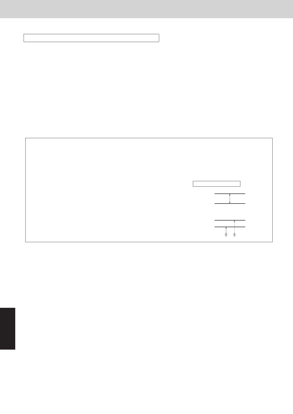
• Measure the line, between wires and ground with the 500 V
mega-tester (insulation resistance meter) and check the values are
over 100MΩ.
• When measuring, be sure to remove both edges of the wire from the
terminal board. If not removed, it will be damaged.
• If the line resistance is within 100MΩ, newly carry out the wiring work.
Between conductors
Line
Between wires and ground
Wire
Wire
Wire
Wire
Ground
SM830289-01_欧州向け R32 mini VRF 8,10HP SM&TRSM.indb 26SM830289-01_欧州向け R32 mini VRF 8,10HP SM&TRSM.indb 26 2021/05/07 10:16:532021/05/07 10:16:53