1 - 35
Mini VRF SYSTEM
Control Functions - Outdoor unit
1
12. Outdoor Unit Control PCB
Table 2
Table 1
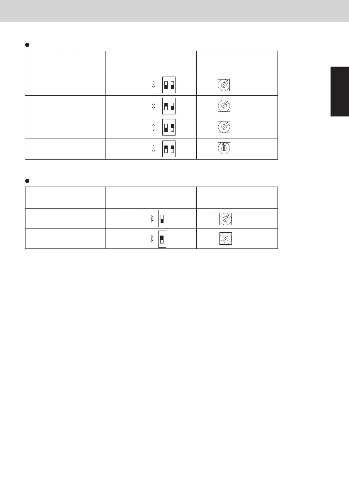
The number of indoor units settings (SW3, SW4)
DO NOT exceed the maximum number of indoor units when making connections.
The indoor unit address setting should also be set less than “16”.
In the event of setting more than “17”, the communication cannot be made between the outdoor and indoor units.
Examples of refrigerant circuit (R.C.) address settings (required when link wiring is used) (SW1, SW2)
System address No.
System address (SW1)
(2P DIP switch)
10 20
System address (SW2)
(Rotary switch)
System 1 (factory setting)
Both OFF
Set to 1 - 9
Set to 0 - 6
21
ON
ON
OFF
Set to 1
System 11
1 ON
21
ON
ON
OFF
Set to 1
System 21
2 ON
21
ON
ON
OFF
Set to 1
System 30
Both ON
21
ON
ON
OFF
Set to 0
Number of indoor units
Indoor unit setting (SW3)
(1P DIP switch)
10
Indoor unit setting (SW4)
(Rotary switch)
10 - 16 unit
(factory setting : 1 unit)
1 - 9 unit
OFF
1
ON
ON
OFF
ON
1
ON
ON
OFF
6
SM830289-01_欧州向け R32 mini VRF 8,10HP SM&TRSM.indb 35SM830289-01_欧州向け R32 mini VRF 8,10HP SM&TRSM.indb 35 2021/05/07 10:10:312021/05/07 10:10:31