27
9 Schematic Diagram
9.1. Schematic Diagram Notes
(All schematic diagrams may be modified at any time with
the development of new technology)
Notes:
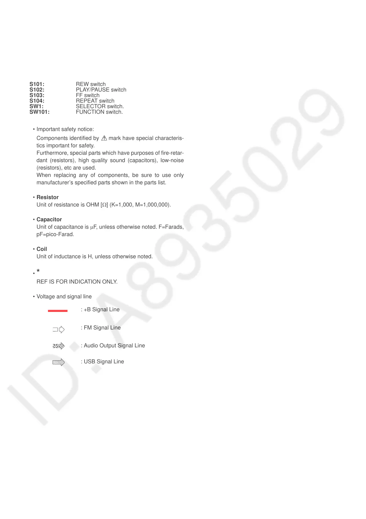
• Important safety notice:
Components identified by mark have special characteris-
tics important for safety.
Furthermore, special parts which have purposes of fire-retar-
dant (resistors), high quality sound (capacitors), low-noise
(resistors), etc are used.
When replacing any of components, be sure to use only
manufacturer’s specified parts shown in the parts list.
• Resistor
Unit of resistance is OHM [Ω] (K=1,000, M=1,000,000).
• Capacitor
Unit of capacitance is μF, unless otherwise noted. F=Farads,
pF=pico-Farad.
• Coil
Unit of inductance is H, unless otherwise noted.
•
*
REF IS FOR INDICATION ONLY.
• Voltage and signal line
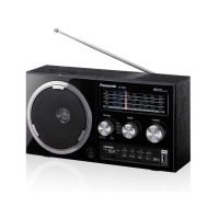
S101: REW switch
S102: PLAY/PAUSE switch
S103: FF switch
S104: REPEAT switch
SW1: SELECTOR switch.
SW101: FUNCTION switch.
: +B Signal Line
: FM Signal Line
: Audio Output Signal Line
: USB Signal Line