41
9 Service Position
Note: For description of the disassembly procedures, see the Section 8
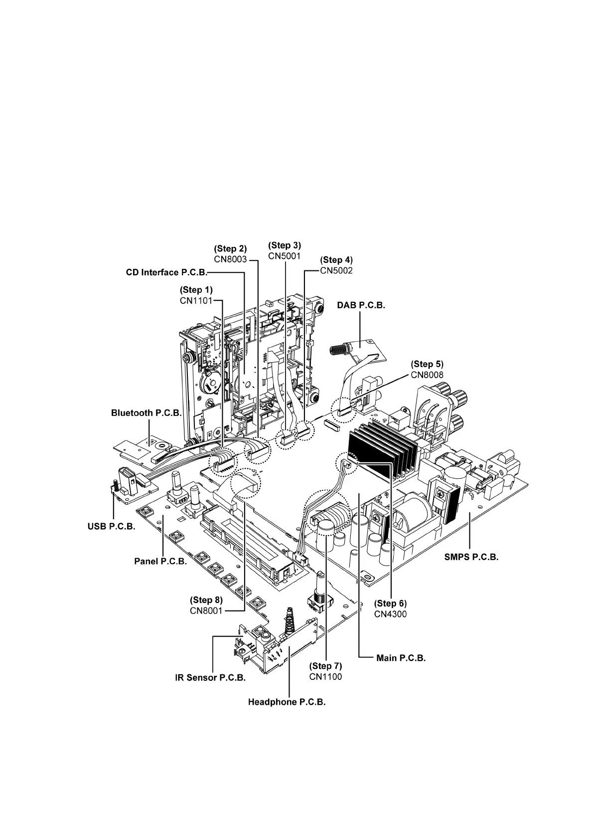
9.1. Checking of Panel, Main, SMPS and CD Interface P.C.B.
Step 1 : Connect 7P wire at the connector (CN1101) on the Main P.C.B..
Step 2 : Connect 9P wire at the connector (CN8003) on the Main P.C.B..
Step 3 : Connect 10P FFC at connector (CN5001) on Main P.C.B..
Step 4 : Connect 24P FFC at connector (CN5002) on Main P.C.B..
Step 5 : Connect 10P FFC at the connector (CN8008) on the Main P.C.B..
Step 6 : Connect 5P wire at the connector (CN4300) on the Main P.C.B..
Step 7 : Connect 15P wire at the connector (CN1100) on the Main P.C.B..
Step 8 : Connect 19P FFC at connector (CN8001) on Main P.C.B..
Step 9 : Check Panel, Main, SMPS and CD Interface P.C.B. according to the diagram shown.