EasyManuals Logo

Panasonic VL-MV26 Installation Guide

Panasonic VL-MV26
122 pages
To Next Page IconTo Next Page
To Previous Page IconTo Previous Page
Page #19 background imageLoading...
Page #19 background image
18
2-5. Lift Controller : VL-V702
2
Role of the VL-V702
Supported control methods
Controlling the destination of lifts
Controlling the destination (floor) of visitors
by linking with the lift and lift control box
Operation Environment : -10 to 50
-1:1 control (Relay Signaling) / Binary control
-Normally Open / Normally Close
-Support up to 100 Floor (up to 3 lifts)
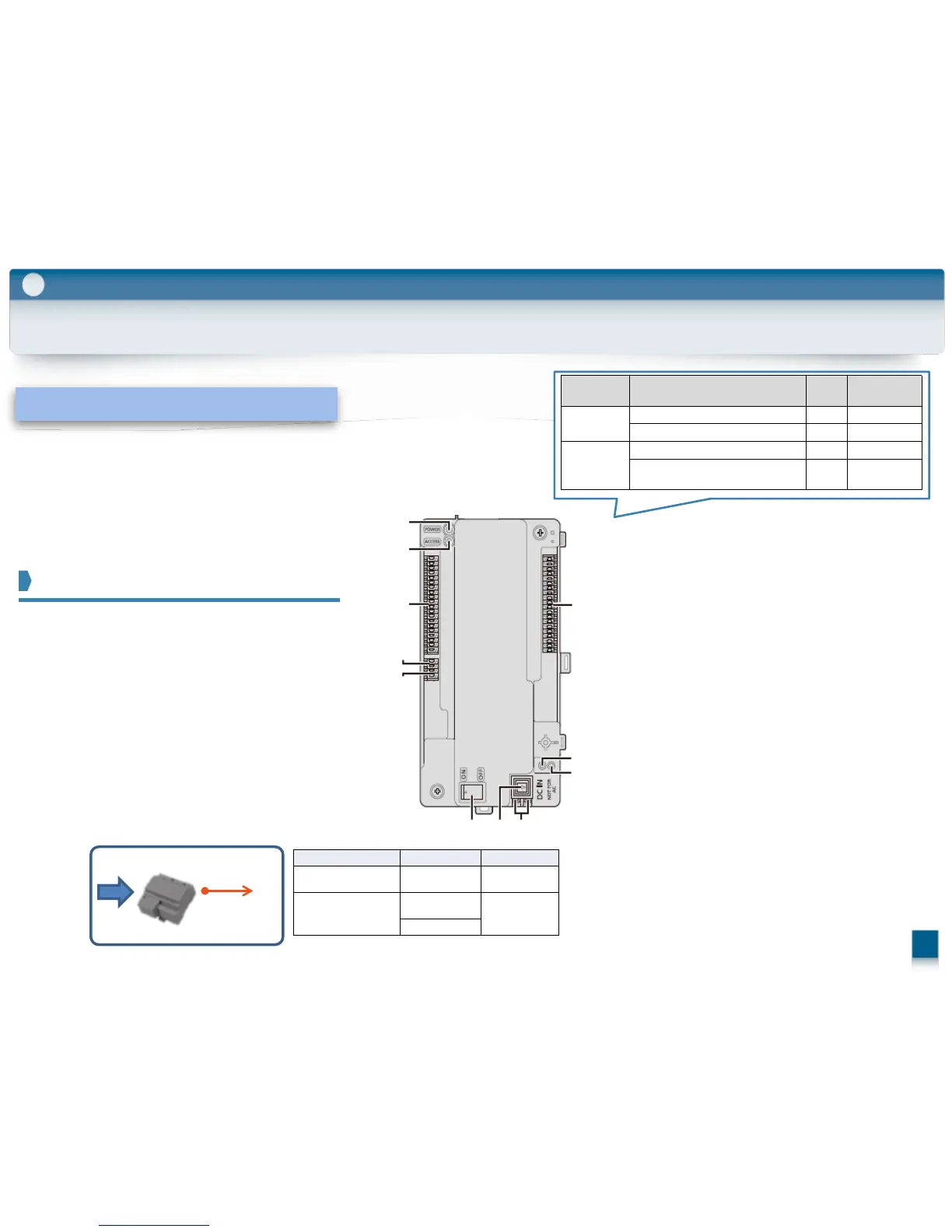
Role/ Features / Installation
(1) Power indicator (POWER)
(2) Access indicator (ACCESS)
(3) Connection terminals for lifts
(4) Connection terminals (input)
for control box or lift controller
(5) Connection terminals (output) for lift
controller
(6) Connection terminals for lifts
(7) Reset button ( )
Used when restarting the lift controller.
(8) Function button (・・)
For internal use only.
(9) Power switch
(10) Cable release button for DC power supply
cable
(11) Connection terminals for DC power supply
Category Meaning
POWER
(GREEN)
ACCESS
(RED)
Idle Lit Off
Call or monitoring in progress Lit Lit
Error
DIP switch 6 or 7 is in the "on" position Off Flashing slowly
Two or more DIP switches are in the
"on" position
Off Flashing slowly
Normal
operation
(1)
(2)
(3)
(4)
(5)
(6)
(7)
(8)
(9) (10) (11)
AC
DC:24V
(11
)
Attached Power Supply Unit
Wiring run Wire diameter Max. length
Power
supply unit
Lift controller
2 mm (12 AWG)
approx. 20 m
Power
supply unit
AC power source
1.2 mm (17
AWG)
No requirement
2 mm (12 AWG)
(Indoor use only)

Table of Contents

Other manuals for Panasonic VL-MV26

Questions and Answers:

Question and Answer IconNeed help?

Do you have a question about the Panasonic VL-MV26 and is the answer not in the manual?

Panasonic VL-MV26 Specifications

General IconGeneral
BrandPanasonic
ModelVL-MV26
CategoryIntercom System
LanguageEnglish

Related product manuals