EasyManuals Logo

Panasonic VL-MV26 Installation Guide

Panasonic VL-MV26
122 pages
To Next Page IconTo Next Page
To Previous Page IconTo Previous Page
Page #20 background imageLoading...
Page #20 background image
2-6. Extension Box : VL-V703
2
Role of the VL-V703
Extend the number of Lobby Station. ( Original 3pcs. Max. Up to 18pcs. )
Operation Environment : -10 to 50
Role/ Features / Installation
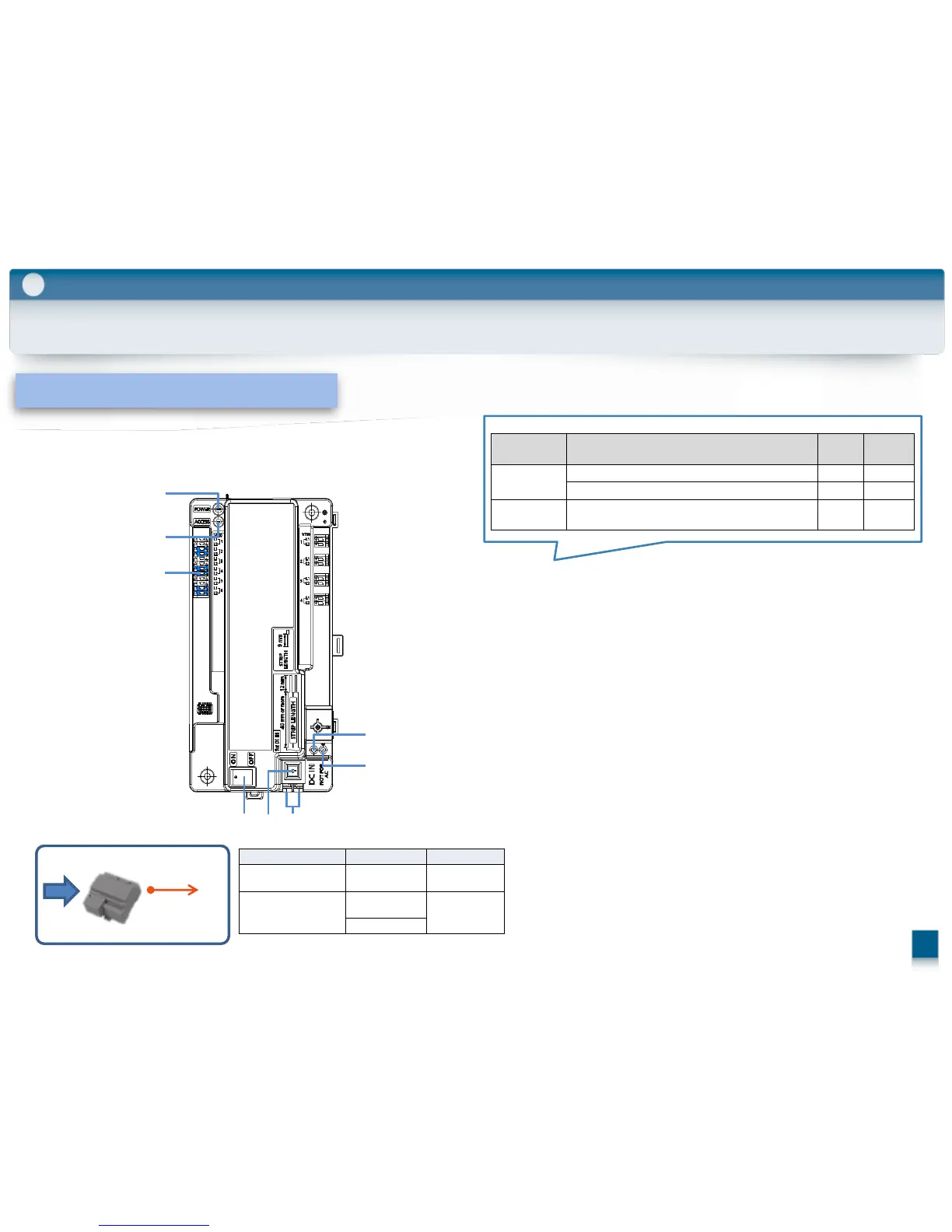
(1) Power indicator (POWER)
(2) Access indicator (ACCESS)
(3) Connection terminals for lobby station
(4) Power switch
(5) Cable release button for DC power supply cable
(6) Connection terminals for DC power supply
(7) Reset button ( )
Used when restarting the extension box.
(8) Function button (・・)
For internal use only.
Category Meaning
POWER
(GREEN)
ACCESS
(RED)
Idle Lit Off
Call in progress Lit Lit
Error
DIP switch 4 or 6 or 7 or 8 is in the "on" position Lit Flashing
Normal
operation
AC
DC:24V
(11
)
Attached Power Supply Unit
Wiring run Wire diameter Max. length
Power
supply unit
Lift controller
2 mm (12 AWG)
approx. 20 m
Power
supply unit
AC power source
1.2 mm (17
AWG)
No requirement
2 mm (12 AWG)
(Indoor use only)
(1)
(2)
(3)
(4) (5) (6)
(7)
(8)
19

Table of Contents

Other manuals for Panasonic VL-MV26

Questions and Answers:

Question and Answer IconNeed help?

Do you have a question about the Panasonic VL-MV26 and is the answer not in the manual?

Panasonic VL-MV26 Specifications

General IconGeneral
BrandPanasonic
ModelVL-MV26
CategoryIntercom System
LanguageEnglish

Related product manuals