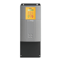
4-25 890CS & 890CD Common Bus Units
890CS Common Bus Supply - Frames B & D; 890CD Common Bus Drive and 890SD Standalone Drive - Frames B, C & D
Control Connections - 890CS Common Bus Supply
The table below shows the factory defaults.
X01
01
+24V AUX
SUPPLY
24V (±10%) 2A
You must supply 24V DC to power the unit.
Use a source separate to your 3∅ supply. Use
the second set of terminals to daisy-chain to
the next drive. Connect three 890CD units
only using this method. The unit is protected
against reversal of this supply. See Note.
02
03
0V AUX
SUPPLY
0V (24V)
04
X02
A 24V DC supply for the digital I/O of X02.
03 ENABLE 0-24V
24V = 890CS Common Bus Supply powers-
up to supply DC to connected units. This is
intended as an aid to functional sequencing
only and must NOT be used as the main
system disable. Personnel must not work on
the system whilst it is held in this state.
05 AOUT MODE 0-24V
0V = Power (kW) , 24V = Current (A).
Selects the units for meter connected to
05 AOUT 0-10V
Mode set by AOUT MODE. Meter
connection:
0 to 5V is equivalent to 0 to 100%.
Note X01: This Control Supply is necessary at all times to operate the 890CS Common Bus
Supply. DO NOT use this 24V for the terminals at X02, only use the 24V supply
provided at X02/01.
230V
400/460V
500V
30
SUPPLY
ENABLE
AOUT MODE
AOUT
0V OUT
HMI - REMOTE
WARNING
HEALTH
PR E-T RIP
S1
 Loading...


