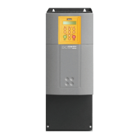
890SD Standalone Drive 5-10
890CS Common Bus Supply - Frames B & D; 890CD Common Bus Drive and 890SD Standalone Drive - Frames B, C & D
Step 2: Connecting Power
In this section we are going to connect the 3-phase supply to the 890SD Standalone Drive(s).
We'll also connect the motor and the (optional) brake resistor.
WARNING
During commissioning, remove the fuses (or trip the circuit breaker) on your 3-phase supply.
Make sure the power is OFF, and that it cannot be switched on accidentally whilst you are working.
Solid-State Short-Circuit Protection
These devices provide Class 10 motor overload protection. The maximum internal overload protection level
(current limit) is 150% for 60 seconds in Constant mode. Refer to Appendix D: Programming - CURRENT
LIMIT for user current limit adjustment information.
Motor over temperature sensing is required where the motor has a full-load Ampere rating of less than 50%
of the drive output rating; or when the MOTOR STALLED trip is TRUE (TRIPS STATUS::DISABLED
WORD 1>>MOTOR STALLED); or when the STALL TIME parameter is increased above 480 seconds.
Motors used in conjunction with the drive controller shall be provided with PTC sensor(s) or relays suitable
for use with the variable speed drive. Technical details can be found in Chapter 5 890SD Standalone Drive.
Refer to the 890 Installation Kit for earth/ground fixing details. Fit the appropriate parts.
Each unit must be permanently earthed according to EN 50178.
For permanent earthing:
A cross-section conductor of at least 10mm² is required. This can be achieved either by using a
single conductor (PE) or by laying a second conductor though separate terminals (PE2 where
provided) and electrically in parallel.
 Loading...


