Čeština
6/20
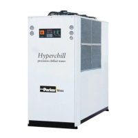
ICEP080E-ICEP120E
4 Ovládání
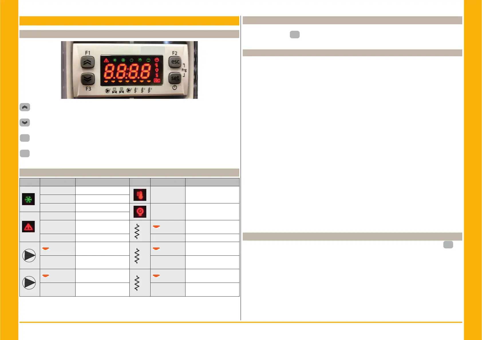
4.1 Ovládací panel
Tlačítko NAHORU: stiskněte pro zvýšení hodnoty vybraného upravitelného parametru.
Tlačítko DOLŮ: stiskněte pro snížení hodnoty vybraného upravitelného parametru.
esc
Tlačítko ESC: k ukončení bez uložení; návrat na předchozí úroveň;STISKNUTO na 5 s. RESET
ALARMU.
set
Tlačítko SET: pro ukončení a uložení/ potvrzení hodnoty; k přechodu na další úroveň; ke vstupu
do nabídky nastavení; STISKNUTO na 5 s. SPUŠTĚNÍ CHLADIČE
4.2 Význam symbolů
Symbol Stav symbolu Funkce Symbol Stav symbolu Funkce
Svítí Kompresor ON
Svítí Hodnota teploty
Bliká Kompresor ve stand-by
Off Kompresor OFF
Svítí Hodnota tlaku
Svítí Aktivní alarm
Bliká
Varování nebo
Resetovatelný alarm
1
Svítí
Protimrazový ohřívač ON
Off Žádný alarm Off Protimrazový ohřívač OFF
1
Svítí
Čerpadlo 1 ON
2
Svítí
Ohřívač klikové skříně ON
Kompresor 1
Off Čerpadlo 1 Off Off
Ohřívač klikové skříně Off
Kompresor 1
2
Svítí
Čerpadlo 2 ON
(není)
2
Svítí
Ohřívač klikové skříně ON
Kompresor 2
Off
Čerpadlo 2 Off
(není)
Off
Ohřívač klikové skříně Off
Kompresor 2
4.3 Starting the chiller
1. Connect the power supply to the machine by turning the main isolator switch QS to ON.
2. Press the button “
set
” to start up.
3. Set the desired temperature on the controller. (par. 4.5.1)
4.3.1 Adjustments at commissioning
1. Water temperature setting, see heading 4.5.
2. Regolation of th pump
Verify correct operation of the pump, using the pressure gauge (read P1 and P0) and checking the
pressure limit values (Pmax and Pmin) indicated on the pump data plate.
P1 = pressure with pump ON
P0 = pressure with pump OFF
Pmin < (P1-P0) < Pmax
- Example n°1.
Conditions:
closed circuit, pressure P0 = 2 bar
pump data plate values: Pmin 1 bar/ Pmax 3 bar
adjust the valve outlet to give a pressure of 3 bar < P1< 5 bar
- Example n°2.
Conditions:
open circuit, pressure P0 = 0 bar
pump data plate values: Pmin 1 bar/ Pmax 3 bar
adjust the valve outlet to give a pressure of 1 bar < P1 < 3 bar
3. Verify correct operation of the pump similarly under normal running conditions.
Check also that the amperage of the pump is within the limits indicated on the data plate.
4. Switch off the chiller and proceed to top up the hydraulic circuit at the “SET” temperature.
5. Check that the temperature of the “treated” water does not fall below 5 °C and that the ambient
temperature in which the hydraulic circuit operates does not fall below 5 °C. If the temperature is
too low, add the appropriate quantity of glycol, as explained under heading 3.3.3.
Y ATTENTION !: before switching on the chiller pump, close the water outlet valve.
Always keep the possible inlet valve open, if present.
After switching on the pump, slowly open the chiller water outlet valve and adjust the fl ow rate as
described in point 4.3.1.
4.4 Stopping the chiller
When chiller operation is no longer required, turn the chiller off as follows: press the button “
set
”(5
Sec.) .
Do not turn off the main switch QS to ensure that any antifreeze protection devices will still receive
electrical power