3
2 Description
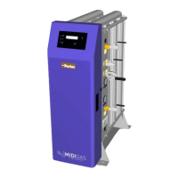
The MIDIGAS range of nitrogen generators operate on the Pressure Swing Adsorption (PSA) principle to produce a continuous stream of
nitrogen gas from clean dry compressed air.
Dual chamber columns, filled with extruded beads of adsorbent (Carbon Molecular Sieve [CMS]) material, are joined via an upper and lower
manifold to produce a two bed system. Compressed air enters the bottom of the ‘on-line’ bed and flows up through the CMS. The oxygen,
carbon dioxide, humidity and non-methane hydrocarbons are preferentially adsorbed by the CMS allowing clean dry nitrogen to pass through.
After a pre-set time the control system automatically switches the bed to regenerative mode. All of the contaminants are vented from the CMS
and a small portion of the outlet nitrogen gas is expanded into the bed to accelerate the regeneration. At the same instant the second bed
comes on-line and takes over the separation process.
The CMS beds alternate between separation and regeneration modes to ensure continuous and uninterrupted nitrogen production.
The oxygen concentration in the nitrogen stream is analysed continuously. If the concentration exceeds the required production level, the
nitrogen outlet is closed and the gas is vented to atmosphere. Normal operation will resume when the purity recovers.
2.1 Technical Specification
Stated flows are for operation at 7 bar g (100 psi g / 0.7 MPa g) with reference to 25ºC.
UNITS 10ppm 100ppm 250ppm 500ppm 0.1% 0.5% 1% 2% 3% 4% 5%
Flowrate
MIDIGAS 2
m
3
/hr
0.55 1.2 1.5 1.9 2.4 3.4 4.3 5.8 7.2 8.4 9.4
cfm 0.3 0.7 0.9 1.1 1.4 2.0 2.5 3.5 4.2 4.9 5.5
MIDIGAS 4
m
3
/hr
1.2 2.4 3.2 3.9 4.7 6.9 8.5 11.6 14.3 16.7 18.8
cfm 0.7 1.4 1.9 2.3 2.8 4.1 5.0 6.8 8.4 9.8 11.1
MIDIGAS 6
m
3
/hr
1.5 3.2 4.2 5.3 6.5 9.5 11.5 15.2 18.7 21.7 24.5
cfm 0.9 1.9 2.5 3.1 3.8 5.6 6.8 8.9 11.0 12.8 14.4
Outlet Pressure bar g 5.6 5.4 5.9 5.7 5.6 5.7 6.0 6.0 5.8 5.7 5.6
psi g 81.2 78.3 85.6 82.7 81.2 82.7 87.0 87.0 84.1 82.7 81.2
Inlet Parameters
Inlet Air Quality ISO 8573-1: 2001 Class 3.2.2
Inlet Pressure
6 – 13 bar g
88 – 188.5 psi g
Inlet Temperature
5 – 50
o
C
(41 – 122
o
F)
Port Connections
Air Inlet G1/2
N
2
Outlet to Buffer
G1/2
N
2
Inlet from Buffer
G1/2
N
2
Outlet
G1/2
Electrical Parameters
Generator Supply
†
115 / 230 ± 10% Vac 50/60 Hz
Generator Power
‡
80 W
Fuse
3.15 A
(Anti Surge (T), 250v, 5 x 20mm HBC,
Breaking Capacity 1500A @ 250v,
IEC 60127, UL R/C Fuse)
Max Dryer Power* 100W
Environmental Parameters
Ambient Temperature
5 – 50
o
C
(41 – 122
o
F)
Humidity
29% @ 50
o
C (80% MAX d 31
o
C)
IP Rating IP20 / NEMA 1
Pollution Degree 2
Installation Category II
Altitude
< 2000 m
(6562 ft)
Noise <80 dB (A)
Packed Weights and Dimensions
Dimensions
mm / (ins)
Weight
Kg / (lbs)
H W D
MIDIGAS 2
612
(24.48)
1490
(59.6)
950
(38)
174
(383.6)
MIDIGAS 4
612
(24.48)
1490
(59.6)
950
(38)
221
(487.2)
MIDIGAS 6
612
(24.48)
1490
(59.6)
950
(38)
272
(597.7)
Notes:
†
The generator does not require adjustment when connecting to 115v and 230v electrical supplies.
‡
The power rating specified is for the generator alone and does not take in to account any pre-treatment dryer connected to the dryer supply terminals of the generator.
* The dryer is fed directly from the generator supply.
 Loading...