8
3 Installation and Commissioning
3.1 Recommended System Layout
3.1.1 Buffer vessel selection
The buffer selection should be sized according to the flowrate of the generator.
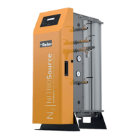
3.1.2 Pre-treatment dryer selection
The following pre-treatment dryers are supplied with filtration and a purge economy lead.
Only competent personnel trained, qualified, and approved by Parker domnick hunter should perform installation,
commissioning, service and repair procedures.
Ref Description Ref Description Ref Description Ref Description
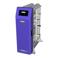
1 Compressor 4 Dryer pre-filtration 7 MIDIGAS generator 10 Dust filter
2 Wet air receiver 5 Pre-treatment dryer 8 Buffer vessel 11 Ball valve
3 Water separator 6 Dust filter 9 Pressure relief valve 12 Drain valve
Pdh part number Flowrate Vessel capacity
m
3
/hr
cfm L
606200238 0 - 3 0 - 1.8 50
606201440 3.1 - 7.5 1.8 - 4.4 150
606201444 7.6 - 12.3 4.5 - 7.2 250
606201450 12.4 - 24 7.3 - 14.1 500
606201452 24.1 - 34 14.2 - 20 750
Outlet Flow Rate m
3
/hr
Model Part Number (230v 50Hz) Part Number (115v 60Hz)
Up to 30
o
C Up to 45
o
C Purge Loss (m
3
/hr)
DAS2 / N2 616200542 616200532 6.3 5.3 1.7
DAS3 / N2 616200543 616200533 10.3 8.3 2.7
DAS4 / N2 616200544 616200534 12.6 10.6 3.4
DAS5 / N2 616200545 616200535 16.5 13.6 4.4
DAS6 / N2 616200546 616200536 18.9 15.9 5.1
DAS7 / N2 616200547 616200537 25.2 22.2 6.8
DME012 / N2 616200203 616200204 38.6 33.1 7.31
DME015 / N2 616200217 616200218 51.3 44.0 9.85
DME020 / N2 616200225 616200226 67.4 57.7 12.91
DME025 / N2 616200233 616200234 85.2 73.0 16.14