Parker Hannin Corporation
Hydraulic Pump and Power Systems Division
Marysville, Ohio USA
Bulletin HY28-2708-02/SVC/EN | July 2019
Medium Pressure Axial Piston Pumps
P1/PD B-mod Service Information
51
A. The B-mod C, L, or AM compensator is the same for both clockwise and
counterclockwise rotation. The compensator position remains unchanged.
B. The port block is bi-rotational, so a new port block is not needed unless the
existing port block is damaged during the rotation change. Therefore, the inlet
and outlet port locations remain the same.
C. For the 45cc and larger pumps, the bias guide (#11) and control guide (#14)
are located into the port block (#3), so they may be difcult to remove without
damaging the guides or port block, so you may want to have extra guides or
port block on hand.
1. Follow the disassembly instructions to the point at which the port plate (#9)
can be accessed. The port plate is rotation dependent and will need to be
changed. See part number tables and select the correct port plate. Use Figure
7 to verify that you have the correct rotation port plate. For the 18, 28, & 45cc
units that are side ported with no thru drive, make sure you select the appro-
priate ripple chamber port plate because those units will have a ripple cham-
ber in the port block as designated by the “R” in the model code description.
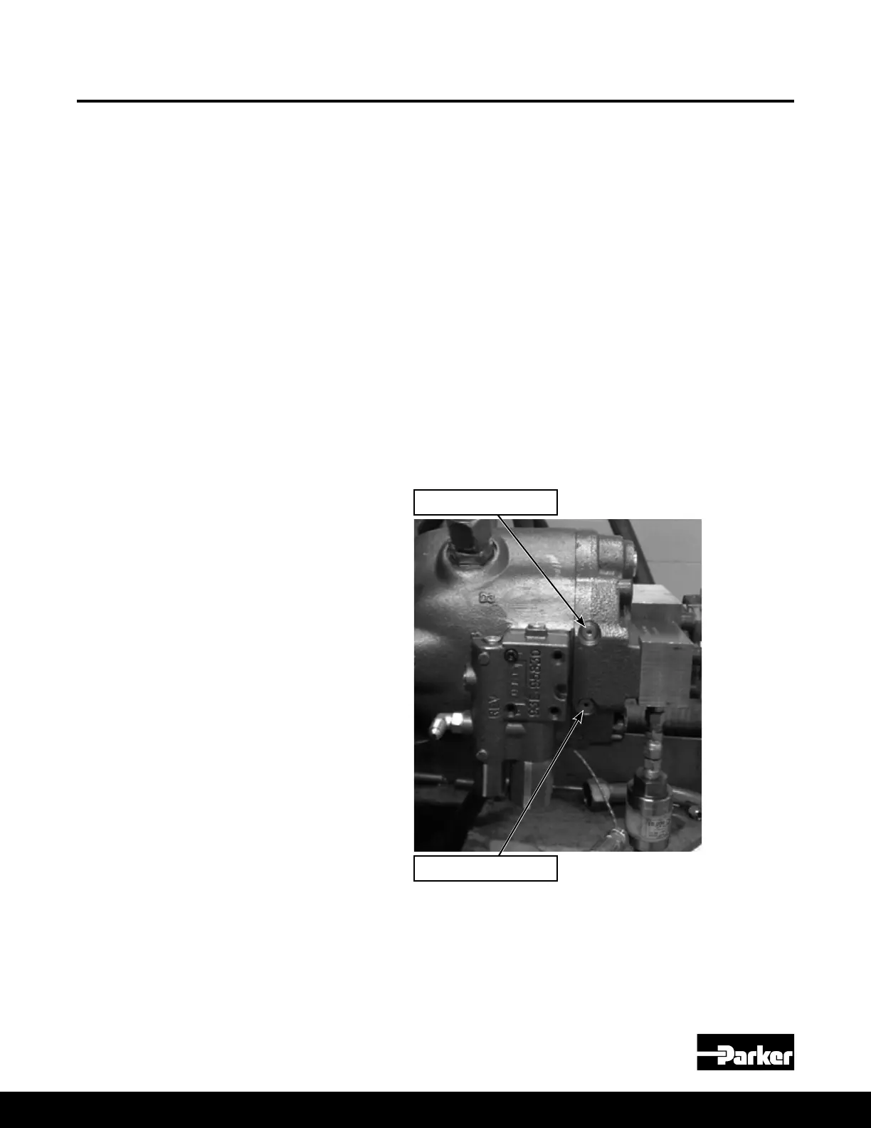
2. Next, the port block control ow set screw (#6) needs to be swapped to the
other passage way as shown in Figure 11. Remove the two boss plugs (#5)
and remove the set screw and install in the other passage. Secure the set
screw with Locktite 243 or equal and torque to 25 in-lbs. Then re-install the
two plugs and torque them to 6 ft-lbs.
Rotation Change Procedure
Figure 11 – Port Block Control Flow Plug Location
3. For 18, 28, 45cc units with ripple chambers, the rippler chamber set screw
(#16) will need to be relocated to the opposite side as show in Figure 6 in the
18, 28, & 45cc assembly procedures. There will only be ripple chambers on
side ported units that do not have a thru drive. Torque the ripple chamber set
screw per the torque values in the torque table on page 6 or 7.
Rotation Change
CCW set screw location
CW set screw location

 Loading...


