Parker Hannin Corporation
Hydraulic Pump and Power Systems Division
Marysville, Ohio USA
Bulletin HY28-2708-02/SVC/EN | July 2019
Medium Pressure Axial Piston Pumps
P1/PD B-mod Service Information
45
11. If the barrel hold down spring (#21) was removed, place the barrel (#23) on
xture with pin side down and install the back-up washer (#22) and hold
down spring. Compress the spring in a press and install the snap ring (#20).
Next, rotate the barrel assembly so that the piston bores face up. Place the
three barrel pins (#24) into the three slots in the barrel spline as shown in
Figure 3. Petroleum jelly can be used to hold the pins in place while installing
the remaining parts.
CAUTION: Make sure the snap ring (#20) is properly seated in the groove
prior to removing the barrel (#23) from the press.
12. Apply a light oil lm into the piston bores of the barrel (#23). Lightly lubricate
the spherical surface of the spherical retaining plate washer (#25). Install
the nine piston bores down (#27) into the bores in the retaining plate (#26).
Assemble the spherical retaining plate washer into the retaining plate.
While holding the spherical washer against the retaining plate, slide the
pistons into the barrel.
13. Install the port block locating/dowel pin (#7) into the port block (#3) face.
14. Install the port block control ow set screw (#6) in the proper location
depending on pump rotation. For proper location, see Figure 11 in the
rotation change section. The set screw should be installed in the passage
on the same side of the port block as the control piston.
15. Install unlubricated O-rings (#10) onto the control piston guide (#14) and
bias guide (#11). Apply Loctite Primer SF 194500 to the control piston guide
and bias guide threads and allow it to dry. This usually take about three
minutes. Apply Loctite 263 to the guide threads. For CW rotation, install the
control piston guide (#14) nearest to the locating pin. See Figure 10A.
For CCW rotation, install the bias guide (#11) nearest to the locating pin (#7).
See Figure 10B. Torque the guides per the values specied in the Table 4.
Table 5
Pump
Control and Bias Guide
Torque
060
105 ± 5 ft-lbs
(142 ± 6.5 Nm)
075 /085
105 ± 5 ft-lbs
(142 ± 6.5 Nm)
100
136 ± 6 ft-lbs
(184 ± 8 Nm)
140
170 ± 6 ft-lbs
(203 ± 8 Nm)
16. Apply a light oil lm to the control piston (#15), and install it into the control
guide (#14) bore. Apply a light oil lm to the bias piston (#12). Install the bias
spring (#13) over the bias guide (#11) bore, and then slide the bias piston into
the bias guide bore.
17. Install the control ow housing set screw (#34) into the proper passage.
For proper location, see Figure 12 in the rotation change section.
18. Apply a light layer of petroleum jelly to the back surface of the port plate (#9)
and place it on the port block (#3), lining up the slot on the port plate with the
locating pin (#7). See Figure 7.
13. Apply a light film of oil into the piston bores. Lightly lubricate the spherical
surface of the guide ball. Install the nine pistons into the bores in the hold
down plate. Install the spherical guide ball into the hold down plate. While
holding the guide ball against the hold down plate, install the pistons into the
barrel.
14. Install the locating pin on the port block face.
15. Apply Loctite Primer Grade T to guide threads and allow to dry. Install
unlubricated o-rings on the control guide and bias guide. Apply Loctite 271to
guide threads. For left hand rotation the bias guide is installed nearest to the
dowel pin (figure 5A.) For right hand rotation the control guide is installed
nearest to the dowel pin (figure 5B.) Torque the control and bias guides as
16. Apply light oil film to control piston and install it in the control guide bore.
NOTE: The 140 had a lubrication hole in the piston. Confirm that the hole is
facing the port block. The control guide has nonsymmetrical lubrication
grooves. The end with the closest grooves must be installed towards the
port block.
17
. Apply light oil film to the bias piston. Install the bias spring and the bias
piston in the bias piston guide bore.
18. Apply a light layer of petroleum jelly to the back surface of the port plate.
Install the port plate on the port block, lining up the slot on the port plate with
the locating pin.
19. Install the large o-ring in the groove on the pump housing. Install the three
Teflon o-rings in the pressure communication ports on the pump housing.
20. Install the cam bearings in the cradle area of the housing. The chamfer on
the back of the bearing must face the outer wall of the housing. Use Loctite
Primer Grade “T” or other suitable primer on screws and mating threads in
housing. Apply Loctite #242 (use sparingly) to screw threads and install
orifice screws to hold bearings in place. Torque screws to 3.4 0.25 Nm (33
3 in-lb).
21. Place thin film of clean oil on cam bearing surfaces. Install cam in housing.
The cam must be tilted to permit entry into the housing. (Figure 2) NOTE:
The large pocket on the bottom surface of the cam must be on the same
side as the three pressure communication holes on the main housing. Pump
rotation does not affect the assembly of the cam.
22. Install the drive shaft into the pump housing. Position pump horizontally.
Install the rotating group over the pump shaft. Rotate the barrel to insure that
it is seated against the cam. Insure that the pump shaft is seated properly in
the front bearing.
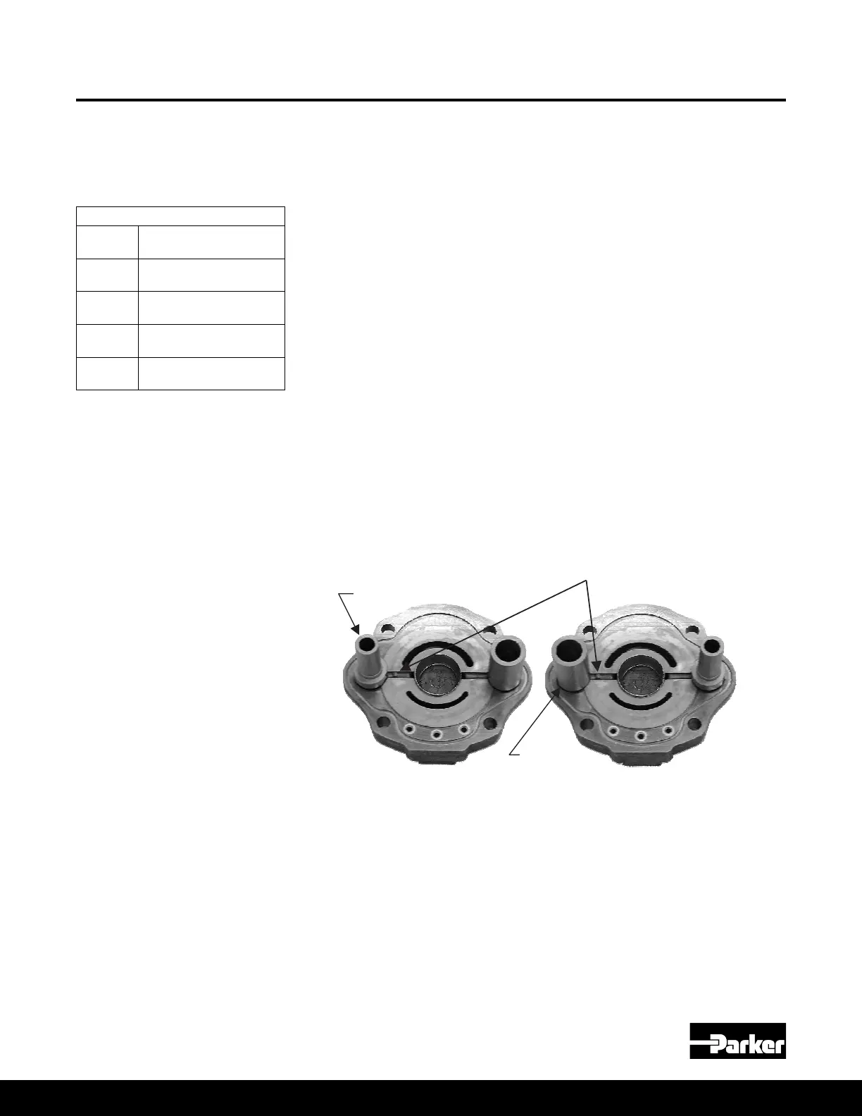
Figure 5A
Port Block with Left
Hand Configuration
Figure 5B
Port Block with Right
Hand Configuration
specified in Chart 3.
Locating Pin
Bias Piston
Guide
Control Piston
Guide
Chart 3
Pump Control and bias
guide torque
045
Figure 10A
Port Block with Left
Hand Conguration
Figure 10B
Port Block with Right
Hand Conguration
Pump Assembly Procedures
(Continued)
060, 075, 085, 100, 140 Assembly Procedures

 Loading...


