Parker Hannin Corporation
Hydraulic Pump and Power Systems Division
Marysville, Ohio USA
Bulletin HY28-2708-02/SVC/EN | July 2019
Medium Pressure Axial Piston Pumps
P1/PD B-mod Service Information
54
2
1
10
9
14
3
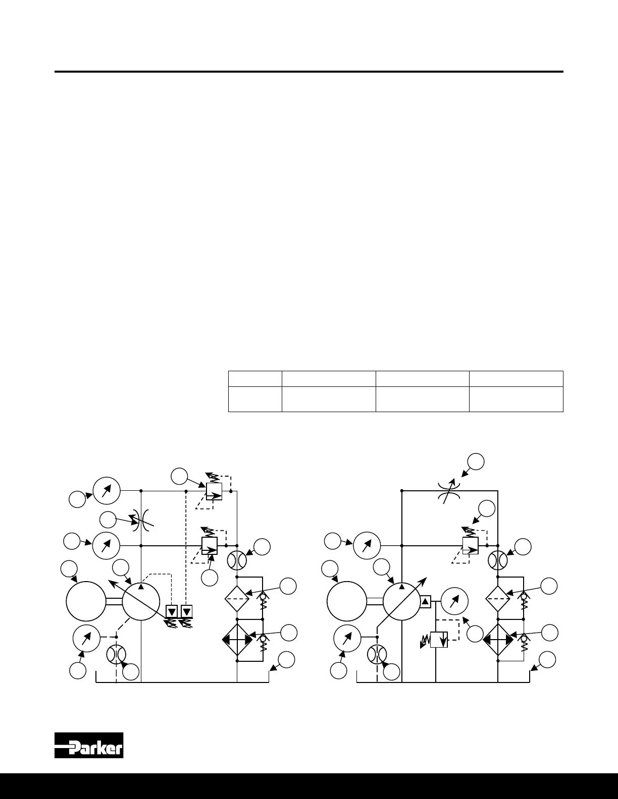
Circuit 2 - Remote Compensator Test Circuit Diagram
EM
13
7
4
11
12
8
EM
2
7
6
4
1
11
12
10
5
9
8
14
3
“X”
Circuit 1 - Load Sense Test Circuit Diagram
Time 60 seconds 60 seconds 60 seconds
Pressure 62-69 bar
900-1000 psi
200-207 bar
2900-3000 psi
269-276 bar
3900-4000 psi
Test Circuit
1. Test pump
2. Test stand prime mover
3. Pump pressure gauge
4. Non-compensating ow control
5. Load pressure gauge
6. Load relief valve
7. Safety bypass relief valve
8. Main ow meter
9. Case drain pressure gauge
10. Case drain ow meter
11. Filter assembly with bypass
12. Cooler assembly with bypass
13. Remote port gauge
14. Reservoir
NOTE: Items 4 and 5 are required for
load sense pump test. Remote relief
valve and remote pressure gauge not
shown for testing "AM" control option.
12. To determine the pump stand-by pressure, reduce the load relief setting to
zero and conrm there is no pressure in the load sense line. The pump outlet
pressure will be the stand-by pressure.
13. Use steps 13-15 for remote compensator pumps (“AM” control option). Close
the load relief valve to deadhead the pump and adjust the remote relief valve
so that the remote port gauge reads at least 300-500psi, and the difference
between the remote and outlet port gauges is greater than the desired
differential pressure setting.
14. Turn the differential screw counter-clockwise so that the difference between
the remote port pressure and the pump outlet pressure equals the desired
differential pressure. Tighten the differential screw lock nut to lock the
differential setting in place. The standard factory differential setting is 20 bar
(290 psi). The minimum allowable setting is 10 bar (145 psi).
15. To determine the pump stand-by pressure, reduce the remote relief setting to
zero and conrm there is little to no pressure in the remote line. There may be
a little pressure depending on the minimum pressure drop across the remote
relief valve. The pump outlet pressure will be the stand-by pressure.
NOTE: For low Pmax settings (around 1000 psi or less), the differential
pressure for the “L” and “AM” controls may not be adjustable. In this case,
raise the Pmax setting to at least 1500 psi and repeat the pressure differential
adjustment steps.
Pump Test Procedure
(Continued)
Test Procedure

 Loading...


