15
P1D Cylinder
05.03
www.parker.com/euro_pneumatic
4,0
3,0
2,0
1,5
1,0
0,5
0,4
0,3
0,2
0,1
1234
5
10 20 30 40 50 100 200 300 500 1000 2000
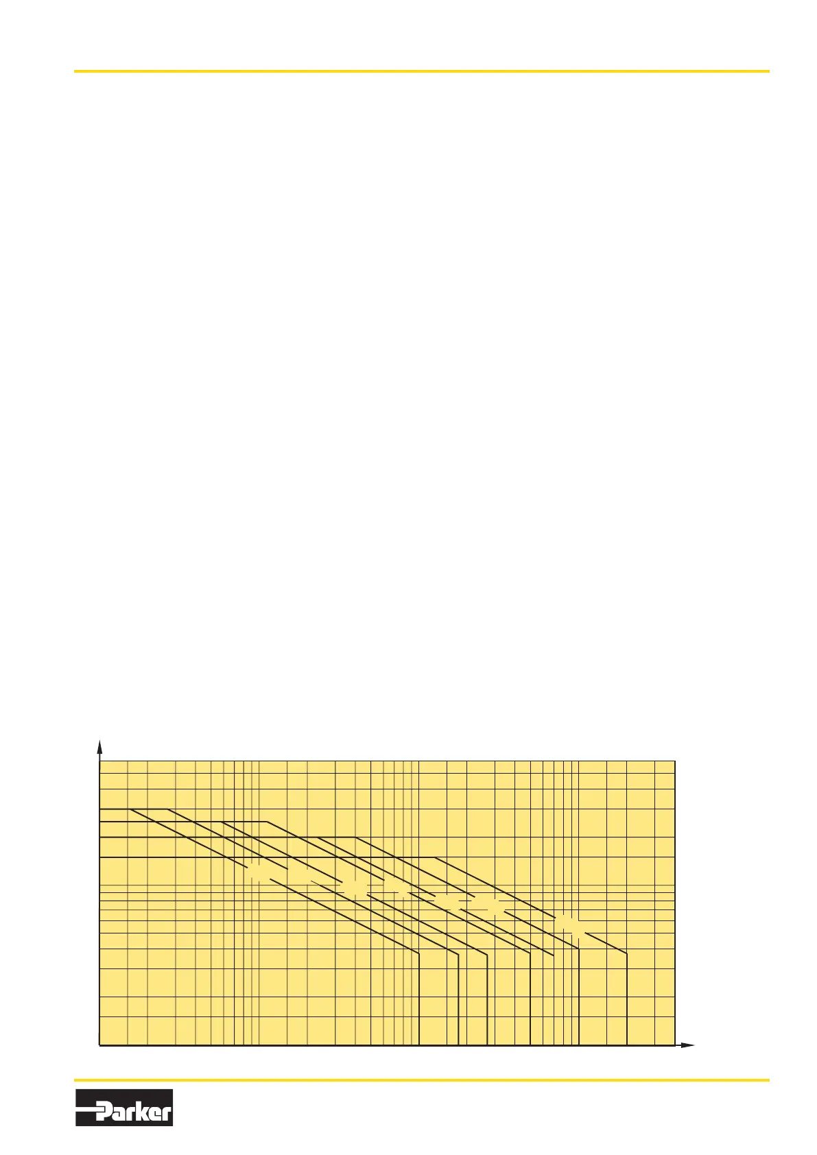
Ø32
Ø40
Ø50
Ø63
Ø80
Ø100
Ø125
Speed [m/s]
Mass [kg]
Material specification
Standard design
Body extrusion Natural colour, anodised aluminium
End cover Black anodised aluminium
End cover inserts POM
End cover nuts/screws Zinc plated steel 8.8
Piston rod nut Zinc plated steel
Piston rod Stainless steel, X 10 CrNiS 18 9
Scraper ring PUR
Piston rod bearing POM
Piston POM
Piston bearing POM
Magnetic ring Plastic bound magnetic material
Piston bolt Zinc plated steel
Piston seal PUR
O-rings Nitrile rubber, NBR
End-of-stroke washers PUR
Cushioning seals PUR
Cushioning screws LCP
P1D Clean
Transparent moulding Silicone
Transparent cover ABS
Screws, sensor system Stainless steel, A2
Upper seal and lower
seal, protective cover Santopren
Sealing plugs PA
Piston rod nut Stainless steel, A2
P1D Flexible Porting
Connection hardware Ø32-63 POM
Elbow fittings Ø32-63 PA
Straight fittings on body extrusion Ø32-63 PA
Straight fittings in ports Nickel plated brass
Seal, connection hardware Nitrile rubber NBR
P1D Tie-Rod
Tie-rods Stainless steel, X 10 CrNiS 18 9
Design variants
Low temperature design
Seals/scraper ring Polyurethane PUR
Piston Anodised aluminium
Piston/piston rod bearing UHMWPE plastic
High temperature design
Seals/scraper ring Fluorocarbon rubber, FPM
Piston Anodised aluminium
Piston/piston rod bearing Bronze filled PTFE
Low pressure hydraulics
Seals/scraper ring Nitrile rubber, NBR
Piston Anodised aluminium
Piston/piston rod bearing UHMWPE plastic
Cylinders for dry rod operation
Seals/scraper ring FPM/HDPE
Option
Piston rod material Hard-chromium plated steel, Fe 490-2 FN
Acid-proof steel, X 5 CrNiMo 17 13 3
Hard-chromium plated stainless steel,
X 10 CrNiS 18 9
Cushioning characteristics
The diagram below is used for dimensioning of cylinders related
to the cushioning capacity. The maximum cushioning capacity
shown in the diagram assumes the following:
• Low load, i.e. low pressure drop across the piston
• Equilibrium speed
• Correctly adjusted cushioning screw
• 6 bar at cylinder port
The load is the sum of internal and external friction, plus any
gravitational forces. At high relative load (pressure drop
exceeding 1 bar), we recommend that for any given speed, the
mass should be reduced by a factor of 2.5, or for a given mass,
the speed should be reduced by a factor of 1.5. This is in relation
to the maximum performance given in the diagram

 Loading...


