EasyManuals Logo

Parker PD-10 Series User Manual

Parker PD-10 Series
286 pages
To Next Page IconTo Next Page
To Previous Page IconTo Previous Page
Page #58 background imageLoading...
Page #58 background image
Parker Hannifin
P series User Guide 56
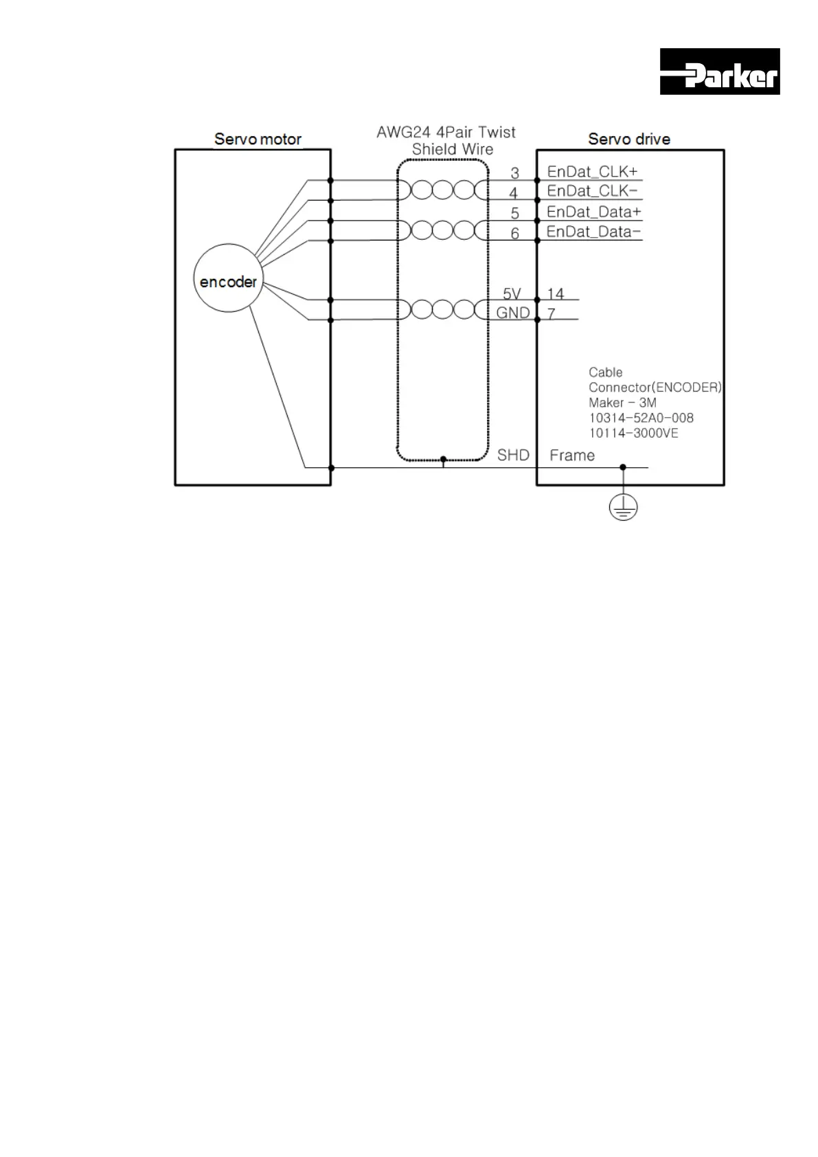
EnDAT2.2 Feedback
3.11.3 I/O Signal Wiring
Example of Digital Input Signal Wiring
Input contact point can be set at Contact Point A or B, depending on the characteristics
of each signal. Each input contact point can be allotted to 28 functions.
Please see 4.5 I/O Signals Setting for signal allotment and contact point change of
input contact points. The service rating is DC12V~ DC 24V.

Table of Contents

Questions and Answers:

Question and Answer IconNeed help?

Do you have a question about the Parker PD-10 Series and is the answer not in the manual?

Parker PD-10 Series Specifications

General IconGeneral
BrandParker
ModelPD-10 Series
CategoryServo Drives
LanguageEnglish

Related product manuals