8200w² Monitor Instruction Manual
4.4 Electrical Installation
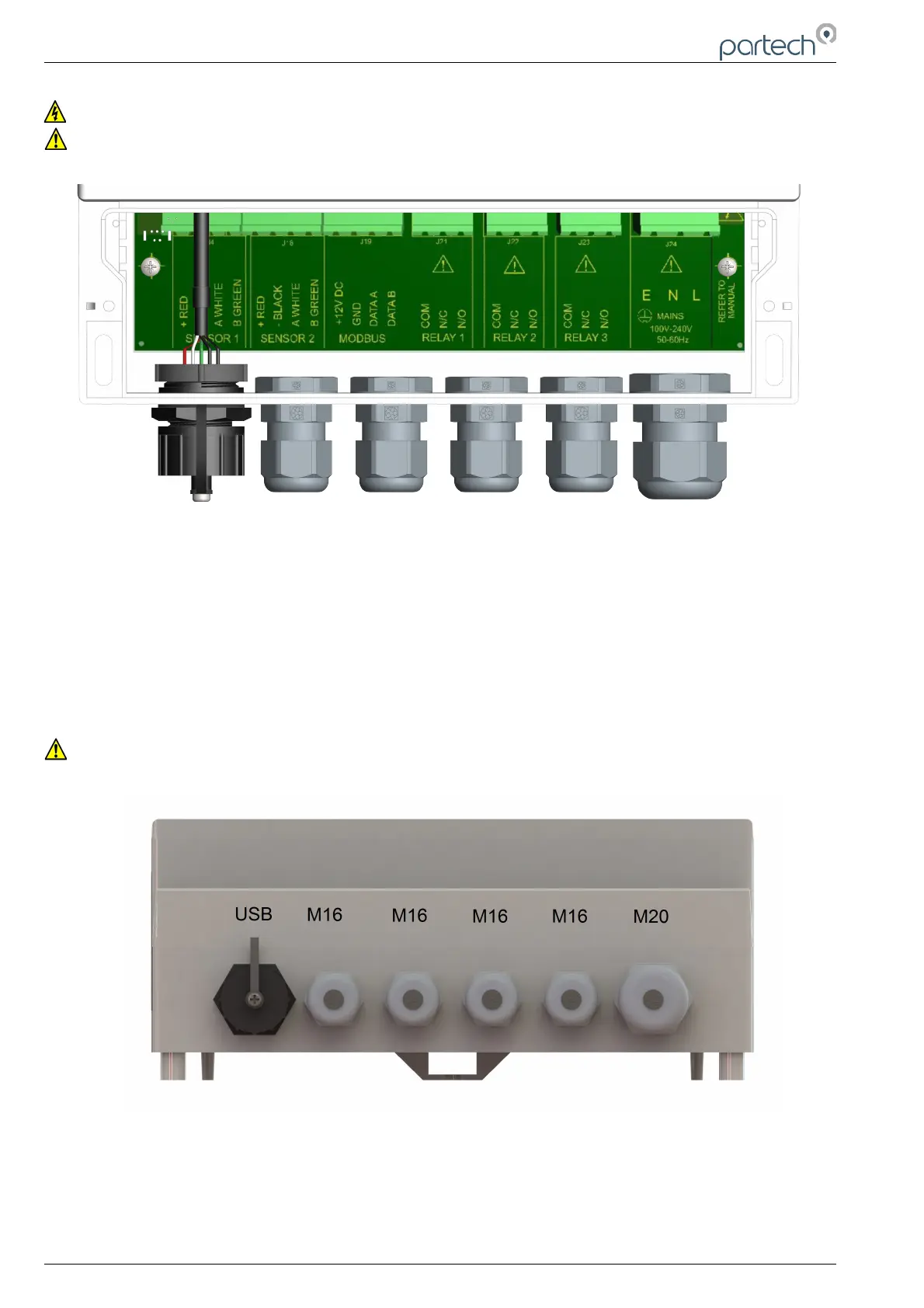
Unscrew the two cover screws on the lower panel of the 8200w² Monitor to reveal the Terminals. Each
terminal strip is labelled as illustrated below. (This equipment must be isolated or disconnected from
HAZARDOUS LIVE voltages before access).
The maximum size wire that can be terminated is 2.5mm² CSA. All the connections are via removable
Plug/Socket terminals. To disengage the terminals, simply pull down to release.
Two power options are available for the 8200w² Monitor, AC and DC. Apart from the supply voltage, all other
connections are identical.
4.4.1 Gland Configuration
The 8200w² Monitor is supplied with IP68 Skintop Nylon glands with lock nuts in the following configuration:
• Left: 1 x USB connection
• Centre 4 x M16 glands (4.5-10mm Ø cable)
• Right: 1 x M20 gland (5-10mm Ø cable)
Gland holes are clearance, not tapped. Always blank unused glands to retain the IP rating of the enclosure
Cabling
When selecting and calculating the mains power cable, please note, an ambient temperature of 60ºC may
see a rise to 80ºC within the terminal compartment. This should be considered when making your
calculations, therefore we recommend a power cable with a maximum rating no less than 80ºC.
Recommended cables include H07RN-F, Steel Wire Armoured or YY, CY or SY types (always check
cable data sheets for maximum temperature ratings, as this can vary between manufactures).
Page 12 of 34 229844IM Issue 01 Issue Date 24/06/2019