8200w² Monitor Instruction Manual
7 Sludge Blanket Level Detection
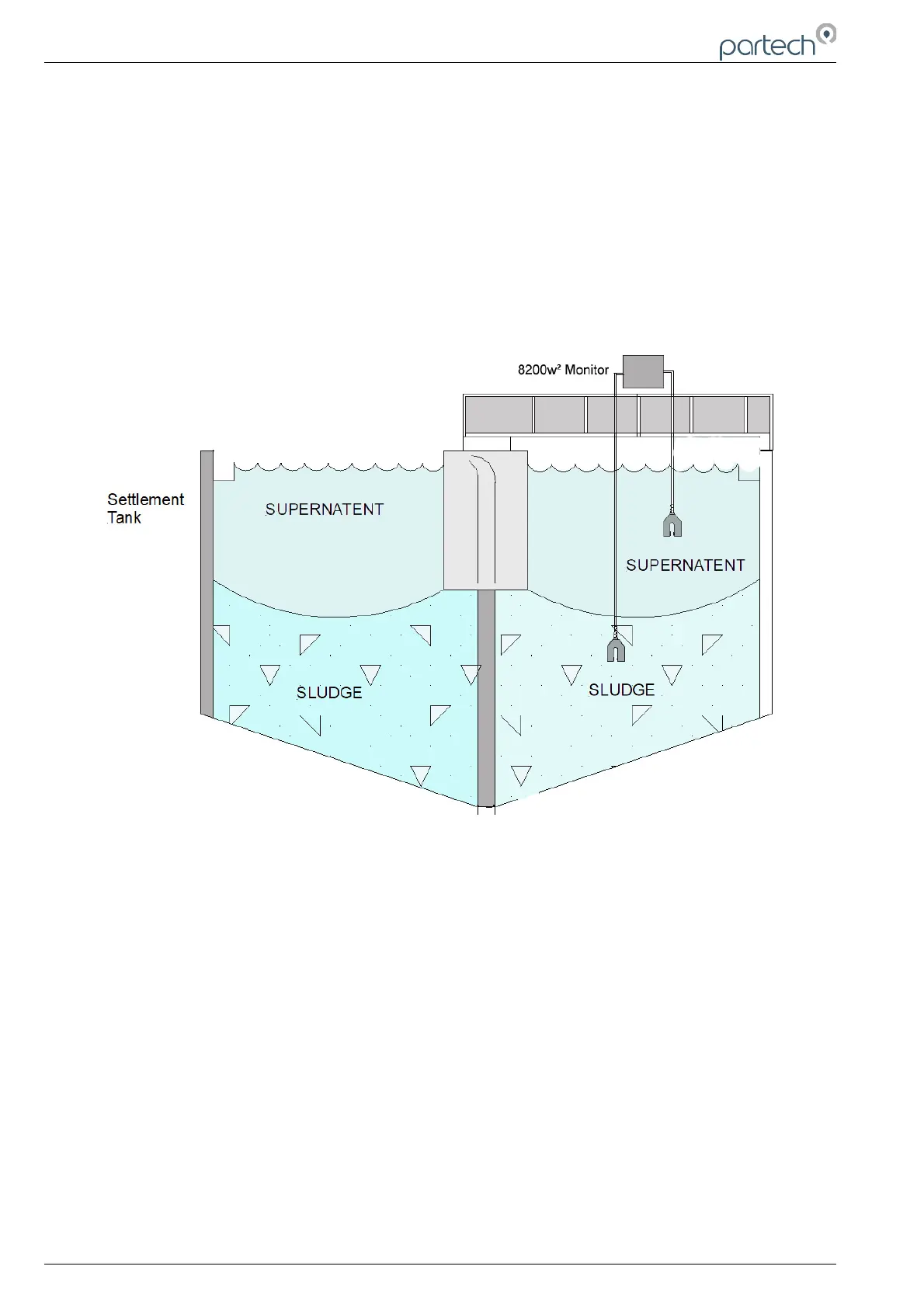
7.1 Description
The typical sludge blanket level detection installation is in a settlement tank. The system is made up of
a single or dual sensor configuration and a monitor. There will also be associated mounting hardware,
which is dependent upon the applications requirements.
The monitor is typically mounted on a handrail on the bridge of a settlement tank. The sensor is
suspended by its cable; though it should be noted that the sensor must be fastened to the fixing point
provided by the mounting bracket and is not left to hang from the cable gland at the base of the
monitor.
When mounting the monitor and sensor on a settlement tank with rotating bridge, the sensor should
normally be located on the leading edge, approximately half way between the centre and outside edge
of the tank, as shown above. Care should be taken when mounting the sensor to ensure that it does
not trail into the scraper.
7.2 Sensor Installation
Once the bracket/monitor has been attached to the handrail via the saddle clamps and U-bolts and the
sensor has been connected to the monitor, it is then a matter of passing the cable through the various
retaining clamps and lowering it into the settlement tank to the desired depth at which the sludge
blanket is required to be detected. When assessing mounting options, attention should be paid to the
accessibility of the sensor for maintenance, stability of the sensor in the flow conditions present on site
and it must also be ensured that when mounting the sensor it is fully submerged at all times.
The sensor can be suspended by its cable, but the top end of the cable must be fastened to a fixed
point. It should be noted that the sensor must not be allowed to hang direct from the cable gland at the
bottom of the monitor.
7.3 Monitor Configuration
When supplied the factory settings may not be suitable for the required application. If this is the case
then the following procedures should be undertaken. Before adjusting the Alarm value settings, ensure
Page 26 of 34 229844IM Issue 01 Issue Date 24/06/2019