6. SERVICE
. ..A. ROLLER SYSTEM...
’
i
4
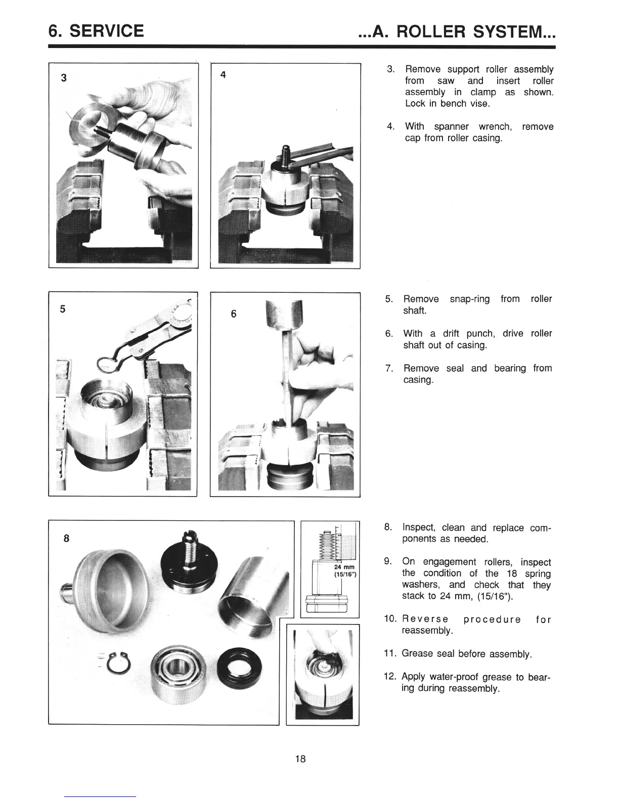
3. Remove support roller assembly
from saw and insert roller
assembly in clamp as shown.
Lock in bench vise.
4. With spanner wrench, remove
cap from roller casing.
5. Remove snap-ring from roller
shaft.
6. With a drift punch, drive roller
shaft out of casing.
7. Remove seal and bearing from
casing.
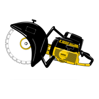
8. Inspect, clean and replace com-
ponents as needed.
9. On engagement rollers, inspect
the condition of the 18 spring
washers, and check that they
stack to 24 mm, (15/16”).
10. Reverse
procedure
for
reassembly.
11. Grease seal before assembly.
12. Apply water-proof grease to bear-
ing during reassembly.
18