6. SERVICE
. ..E. HYDRAULIC SYSTEM...
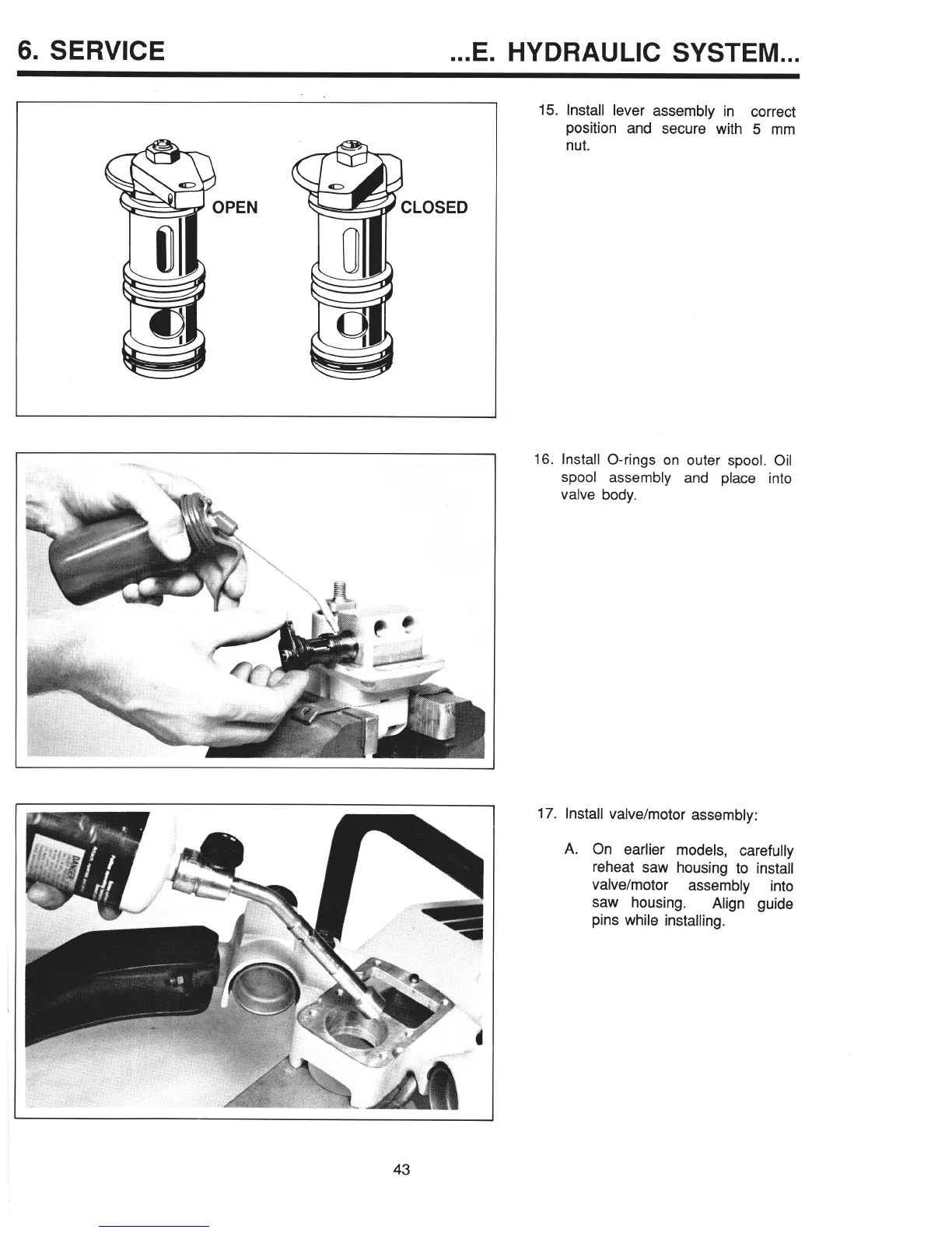
15. Install lever assembly in correct
position and secure with 5 mm
nut.
’
PEN
LOSED
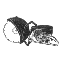
16. Install O-rings on outer spool. Oil
spool assembly and place into
valve body.
17. Install valve/motor assembly:
A. On earlier models, carefully
reheat saw housing to install
valve/motor assembly
into
saw housing.
Align guide
pins while installing.
43