Home
Partner
Touch terminals
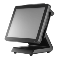
PT-5910
Page 60 (Front Cover)
Partner PT-5910 - Front Cover
74 pages
Manual
Save Page as PDF
To Next Page
To Next Page
To Previous Page
To Previous Page
Loading...
52
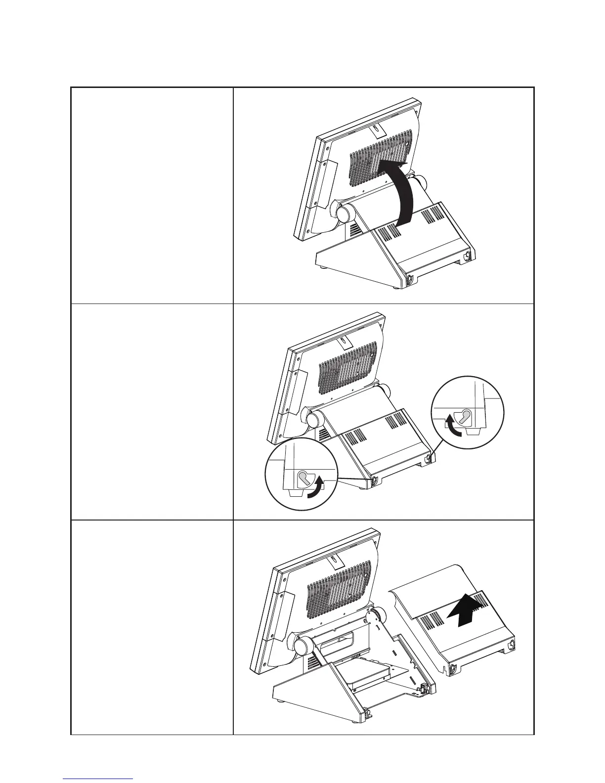
CHAPTER 5 REPLACING FIELD REPLACEABLE UNITS (FRUs)
Front Cover
1.
Rotate the LCD screen forward .
2.
Open the rear cover latches.
3.
Remove the rear cover
.
4.
Disconnect the power cable and
SA
T
A
cable from the hard drive.
59
61
Table of Contents
Main Page
Default Chapter
3
Declaration of Conformity
3
About this Manual
4
Revision History
4
Table of Contents
5
Chapter 1 Getting Started
9
Unpacking the Machine
9
Figure 1.1 Unpacking the Machine
9
Identifying Components
10
Figure 1.2 Front-Right View
10
Figure 1.3 Rear View
11
Figure 1.4 PT-5910 I/O Connectors
12
Chapter 2 Bios Setup
13
About the Setup Utility
13
Entering the Setup Utility
14
BIOS Navigation Keys
14
Figure 2.1 Main BIOS Screen
14
Using BIOS
15
Main Screen
16
Figure 2.2 Main Screen
16
Advanced Settings
17
Figure 2.3 Advanced Settings Screen
17
Figure 2.4 IDE Configuration Sub-Menu
18
IDE Configuration
18
Figure 2.5 Primary/Secondary IDE Master Sub-Menu
19
Primary/ Secondary IDE Master
19
Figure 2.6 MPS Configuration Sub-Menu
20
MPS Configuration
20
Figure 2.7 Superio Configuration Sub-Menu
21
Superio Configuration
21
Figure 2.8 Hardware Health Configuration Sub-Menu
22
Hardware Health Configuration
22
ACPI Configuration
23
Figure 2.9 ACPI Settings Sub-Menu
23
Figure 2.10 USB Configuration Sub-Menu
24
USB Configuration
24
Boot Settings Configuration
25
Figure 2.11 Boot Settings Screen
25
Boot Device Priority
26
Figure 2.12 Boot Device Priority Sub-Menu
26
Figure 2.13 Hard Disk Drives Sub-Menu
27
Hard Disk Drives
27
Boot Settings Configuration
28
Figure 2.14 Boot Settings Configuration Sub-Menu
28
Chipset Settings
29
Figure 2.15 Chipset Settings Screen
29
Figure 2.16 North Bridge Chipset Configuration Sub-Menu
30
North Bridge Chipset Configuration
30
Figure 2.17 South Bridge Chipset Configuration Sub-Menu
31
South Bridge Chipset Configuration
31
Security Settings
32
Figure 2.18 Security Settings Screen
32
Exit Menu
33
Figure 2.19 Exit Menu Screen
33
Load Failsafe Defaults
34
Chapter 3 Installing Drivers and Software
35
Driver Auto Installation
35
Intel Chipset Driver
36
Intel Chipset Graphics Driver
38
HD Audio Driver
40
LAN Driver
41
Touch Screen Driver
43
Calibrating the Touchscreen
46
Chapter 4 Locating the Problem
49
General Checkout Guidelines
49
Cash Drawer Checkout
49
LCD Symptoms
50
Figure 4.1 Connecting a Cash Drawer
50
Touch Screen Symptoms
51
Power Symptoms
51
Network Symptoms
51
USB Symptoms
52
Peripheral-Device Symptoms
52
Boot Symptoms
52
Mainboard Jumper
53
Figure 4.2 PT-5910 Mainboard Jumper
53
Mainboard Connectors
54
Inverter Connectors
54
Figure 4.3 PT-5910 Mainboard Connectors
54
Figure 4.4 Inverter Connectors
54
CHAPTER 5 REPLACING FIELD REPLACEABLE UNITS (Frus)
55
Safety and Precautions
55
Before You Begin
56
Replacing Parts
56
Msr
57
Customer Display
57
Hdd
58
Front Cover
60
Speaker Bracket
62
Speaker
62
Power Button
62
Memory
63
Battery
63
LPT Port, PS/2 Port, DC 12V Connector and Audio Jacks
63
Mainboard Board
64
I/O Shield
65
Inverter
66
Panel Bracket
67
Waterproof Seal, Touch Panel, Touch Cover, LCD Panel
67
Appendix Part List and Specification
69
Figure 6.1 Exploded Diagram Main Parts
69
Figure 6.2 Exploded Diagram Main Parts
70
Figure 6.3 Exploded Peripheral Parts
71
Part List for PT-5910
72
Part List for PT-5910 Option
73
Specifications
74
Related product manuals
Partner PT-6212
72 pages
Partner PT-6212-EB
2 pages
Partner PT-6215-ES
2 pages
Partner SP-800
70 pages
Partner SP-850
2 pages
Partner SP-550
2 pages
Partner SP-820
50 pages
Partner SP-1030
80 pages
Partner SP-1060
2 pages
Partner SP-630-Q
73 pages
Partner SP-1000-C
46 pages
Partner SP-1000-BZ
50 pages