VENTING & AIR INLET PIPING
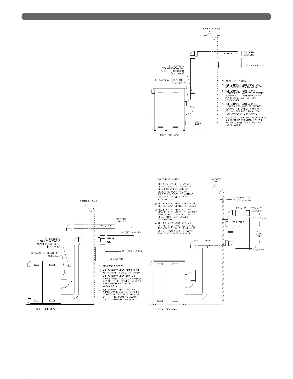
b. Figure 3.3, 3.4 and 3.5 show approved sidewall
venting configurations using standard PVC or
CPVC fittings. A similar configuration using
FasNSeal stainless steel exhaust pipe can be used
with either PVC or other approved material for the
combustion air intake piping.
8. Figures 3.6 through 3.8 show recommended vertical
venting configurations.
a. Figure 3.6 illustrates a vertical venting
configuration using PVC inlet and exhaust. A
similar configuration can be constructed using a
FasNSeal stainless steel vent termination. PVC or
other approved materials may be used for air inlet
piping.
i. The opening of the air inlet piping is to be a
minimum of 12" (300 mm) above the
expected snow accumulation on the roof
surface or 24" (600 mm) above the roof
surface, whichever is greater.
ii. Locate the opening of the exhaust vent pipe a
minimum of 12" above the air inlet opening to
prevent flue gas from recirculating to the air
inlet.
b. Figure 3.7 shows vertical exhaust venting through
an unused chimney. In this case, combustion air is
supplied from inside the building. Section 1.D
provides guidelines for determining adequate
inside air.
c. Figure 3.8 illustrates another vertical venting
configuration through an unused chimney. In this
arrangement the combustion air is supplied
through the chimney as well.
Figure 3.3: Sidewall Exhaust Vent and Air Inlet Pipe
Figure 3.5: Offset Sidewall Exhaust Vent and Air
Inlet Pipe
Figure 3.4: Sidewall Exhaust Vent with Indoor Air
10