27
k. Turn the internal screw clockwise to close the
valve.
l. Turn on the gas shutoff valve and the boiler
service switch.
m. Start the boiler and check for fuel gas odor
around the gas valve. If an odor is evident, check
to make sure that the pressure tap fitting is closed.
n. Repeat this procedure on the second gas valve.
4. All gas piping must be leak tested prior to placing the
boiler in operation.
a. If the required leak test pressure is higher than 26
in. w.c., the boiler must be isolated from the gas
supply piping by closing the service valve.
b. If the gas valve is exposed to pressure exceeding
26 in. w.c., the gas valve must be replaced.
5. Install the boiler such that the gas ignition system
components are protected from water (dropping,
spraying, rain, etc.) during operation and service
(circulator replacement, condensate collector and
neutralizer clean out, control replacement, etc.).
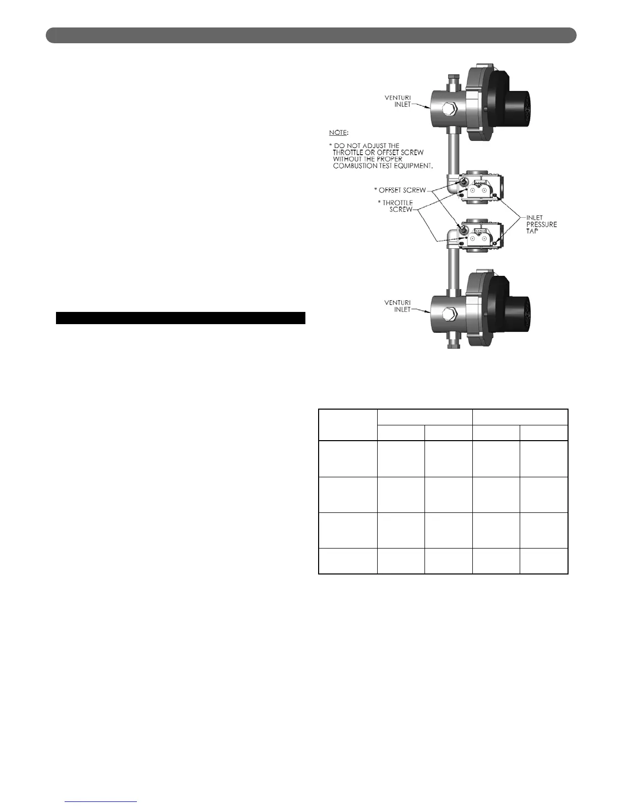
E. MAIN GAS VALVES - OPERATION
1. Figure 5.2 is an illustration of the main gas valve,
venturi and blower assembly for the P
UREFIRE
®
boiler.
2. Do not make adjustments to the gas valve without
instrumentation to measure carbon dioxide (CO
2
) and
carbon monoxide (CO) emissions in the exhaust vent
pipe.
3. Turning the throttle screw clockwise will decrease the
gas flow (decreasing CO
2
) and turning it
counterclockwise will increase the gas flow rate
(increasing CO
2
). Markings adjacent to the throttle
screw show + and – indicating this operation.
a. Throttle adjustments should be made only at full
input rate with the other burner off.
b. The exhaust emissions should be checked with
both burners in operation to assure correct
operation.
c. See Section 9, Start-Up Procedure for specific
information about commissioning and adjusting
the boiler.
4. The recommended CO
2
settings are given in Table
5.5. In no case should the boiler be allowed to
operate with CO emissions higher than 150 ppm.
5. Refer to Section 3, Venting and Air Inlet Piping for
information on obtaining exhaust vent samples from
this boiler.
FUEL PIPING
Figure 5.2: Gas Valve, Venturi and Blower Assembly
Natural Gas Propane (LP)
Low Fire High Fire Low Fire High Fire
Carbon
Monoxide
(CO)
< 50 ppm < 100 ppm < 50 ppm < 100 ppm
Carbon
Dioxide
(CO
2
)
8.8% to
10.0%
8.5% to
9.5%
9.8% to
11.0%
9.5% to
10.5%
Excess
Oxygen
(O
2
)
3.4% to
5.4%
4.2% to
6.0%
4.2% to
6.0%
4.9% to
6.5%
Excess Air
17.3% to
31.0%
22.4% to
35.8%
22.4% to
35.8%
27.3% to
40.1%
Table 5.5: Recommended CO
2
Settings