D. EXHAUST VENT/AIR INTAKE PIPE SIZING
1. PUREFIRE
®
boiler models PF-850 and PF-1000 are to
be installed using 6" piping for both exhaust and air
inlet. A list of approved materials for the exhaust are
in Table 3.1 and a list of approved materials for air
inlet are in Table 3.2
2. The total combined length of exhaust vent and air
intake piping is 200 equivalent feet (60 m).
a. The P
UREFIRE
®
PF-850 and PF-1000 may be
provided with room air as long as there is
adequate combustion and ventilation air provided.
See Section 1.D: Combustion and Ventilation Air
of this manual for the minimum requirements. In
this case, a maximum of 200 equivalent feet of
exhaust vent pipe can be used.
b. The equivalent length of elbows, tees and other
fittings are listed in Table 3.3.
c. The total equivalent length can be calculated as
shown in Table 3.4.
E. EXHAUST VENT/AIR INTAKE
INSTALLATION
1. Figure 3.10 shows the exhaust connection on the rear
of the boiler on the vertical centerline. The exhaust
connection is a 6" FasNSeal stainless steel connection.
2. A 6" FasNSeal stainless steel boot tee with a drain
fitting is included with each PF-850 & PF-1000 boiler.
This should be connected directly to the rear of the
boiler as shown below.
3. The Air Intake connection is a 6" galvanized collar to
the right and below the exhaust connection. This can
be connected to any of the approved air intake piping
materials.
4. The Air Intake connection should be secured with (3)
screws and sealed.
5. Remove all burrs and debris from the joints and fittings.
6. Care should be taken to prevent dirt or debris from
entering the air intake connection. A screen is
provided inside the Air Intake fitting to prevent large
objects from entering the combustion system.
7. Horizontal lengths of exhaust vent must be installed with
a slope of not less than 1/4" per foot (21mm per meter)
toward the boiler to allow condensate to drain from the
vent pipe. If the vent pipe must be piped around an
obstacle that causes a low point in the piping, a drain
with an appropriate trap must be installed.
Les sections horizontales de l’évacuation doivent être
installées avec une pente d’au moins 1/4 po au pied
(21 mm par mètre) en direction de la chaudière afin
que le condensat puisse s’évacuer du tuyau
d’évacuation. Si le tuyau d’évacuation est acheminé
autour d’un obstacle qui crée un point bas dans la
tuyauterie, il est nécessaire alors d’installer un drain
équipé d'une vidange adéquate.
8. All piping must be fully supported. Use pipe hangers
at a minimum of 4 foot (1.22 meter) intervals to
prevent sagging of the pipe.
Tous les tuyaux doivent être parfaitement soutenus.
Utiliser des attaches de tuyau tous les 4 pieds (1,22
mètres) pour éviter le fléchissement des tuyaux.
9. Exhaust and air inlet piping is to be supported
separately and should not apply force to the boiler.
Les tuyaux d’évacuation et d’arrivée d’air doivent
avoir des dispositifs de support distincts et ne pas
exercer de pression sur la chaudière.
10. Penetration openings around the vent pipe and air
intake piping are to be fully sealed to prevent exhaust
gases from entering building structures.
11. PVC & CPVC Piping:
a. Use only solid PVC or CPVC Schedule 40 or 80
pipe for exhaust venting. Cellular core PVC or
CPVC is not approved for exhaust vent.
b. All joints in vent pipe, fittings, attachment to the
boiler stub, and all vent termination joints must be
properly cleaned, primed and cemented. Use only
cement and primer approved for use with PVC or
CPVC pipe that conforms to ANSI/ASTM D2564.
c. A PVC or CPVC coupling can be used as an
outside vent termination. In this configuration,
place one of the 6" diameter screens provided
between the coupling and exhaust connection
before gluing it. This is intended to prevent birds
or rodents from entering.
d. A PVC or CPVC tee can be used as an outside air
intake termination. When using this configuration,
place one of the 6" diameter screens provided
between the tee and the air inlet connection
before gluing it. This is intended to prevent birds
or rodents from entering.
VENTING & AIR INLET PIPING
This appliance uses a positive pressure venting
system. All joints must be sealed completely to
prevent leakage of flue products into living spaces.
Failure to do this may result in severe personal injury,
death or major property damage.
WARNING
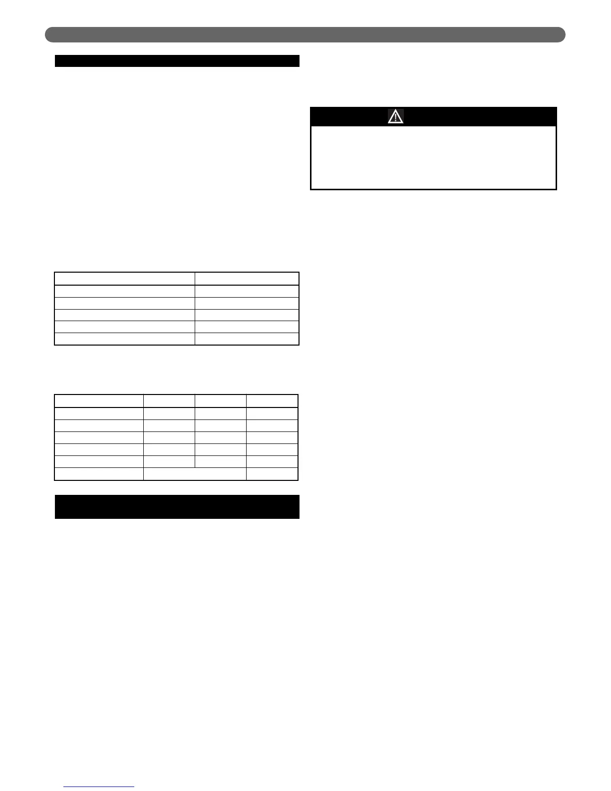
Exhaust Air Inlet Total
Straight Length of Pipe 100' 50' 150'
90° Elbows, SR 2 x 5'= 10' 1 x 5' = 5' 15'
45° Elbows, SR 2 x 3' = 6' 6'
Air Intake Tee 0' 0'
Outlet Coupling 0' 0'
Total 171'
Table 3.4: Sample Equivalent Length Calculation
Table 3.3: Equivalent Length of Fittings
Fitting Description Equivalent Length
Elbow, 90° Short Radiusz 5 feet (1.5 m)
Elbow, 90° Long Radius 4 feet (1.2 m)
Elbow, 45° Short Radius 3 feet (0.9 m)
Coupling 0 feet (0 m)
Air Intake Tee 0 feet (0 m)
12