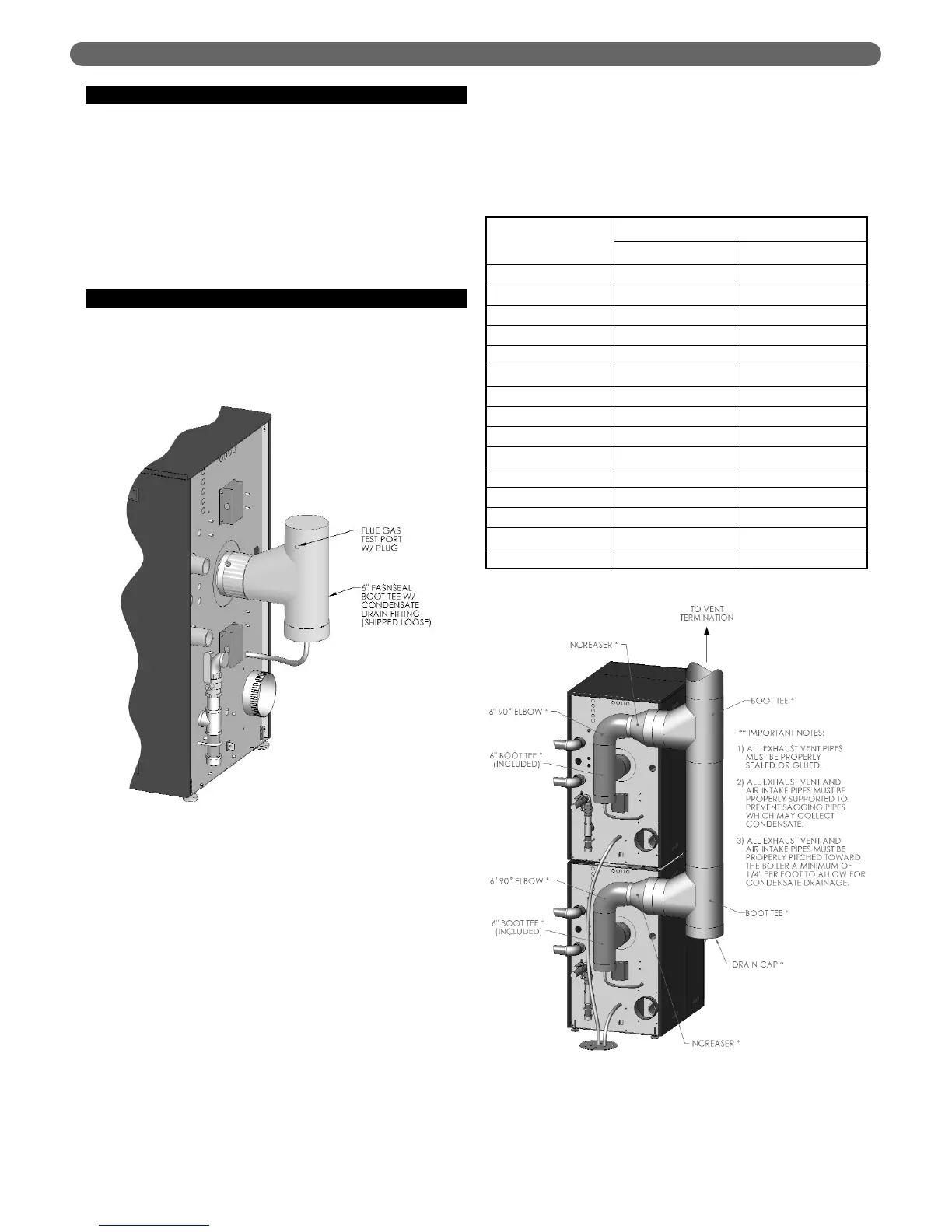
F. TEST PORT FOR EXHAUST SAMPLING
1. Figure 3.10 shows an illustration of the plugged
sample port on the outlet of the drain tee for the PF-
850 and PF-1000 boiler.
2. To obtain an exhaust sample during operation,
remove the test port plug and insert the probe from a
suitable combustion analyzer.
3. Be sure to replace the plug before leaving the boiler
unattended.
G. COMMON VENTING MULTIPLE BOILERS
1. Multiple PUREFIRE
®
PF-850 and PF-1000 boilers may
be connected to a common vent system if they are set
up to operate in the cascade mode described in
Section 8.
a. The boilers must communicate in a
Master/Dependent relationship provided in the
system software.
b. The backflow prevention valves supplied on the
gas/air premix inlet prevent products of
combustion from backing up through the burners
into occupied space.
c. A safety control algorithm will operate the blower
to prevent backflow in case of a backflow
prevention valve failure.
2. Figure 3.11 shows two P
UREFIRE
®
PF-850 boilers
connected with a common vent system.
a. The drain tee from the common vent section
should be trapped and neutralized separately from
the boilers.
b. The condensate drain from each boiler should be
run separately to the drain system to prevent a
clogged condensate line from shutting down
multiple boilers.
c. Table 3.5 shows recommended sizing for common
vent piping.
VENTING & AIR INLET PIPING
Figure 3.11: Multiple Boilers with Common Venting
Table 3.5: Common Exhaust Vent Sizing
Figure 3.10
Number
of Boilers
Boiler Model
PF-850 PF-1000
2 8" 9"
3 10" 12"
4 12" 12"
5 14" 14"
6 14" 16"
7 16" 16"
8 16" 18"
9 18" 18"
10 18" 20"
11 20" 20"
12 20" 22"
13 20" 22"
14 22" 24"
15 22" 24"
16 24" 24"
13