30
A. GENERAL
This appliance is to be wired in accordance with local
codes and regulations as defined by the Authority having
jurisdiction. In the absence of such local codes, the
P
UREFIRE
®
boiler is to be wired in accordance with the latest
edition of the National Electrical Code, ANSI/NFPA 70.
The boiler must be electrically bonded to ground in
accordance with the requirements of the authority having
jurisdiction or, in the absence of such requirements, with the
National Electrical Code, ANSI/NFPA 70, and/or the
Canadian Electrical Code Part I, CSA C22.1, Electrical Code.
B. CUSTOMER CONNECTIONS
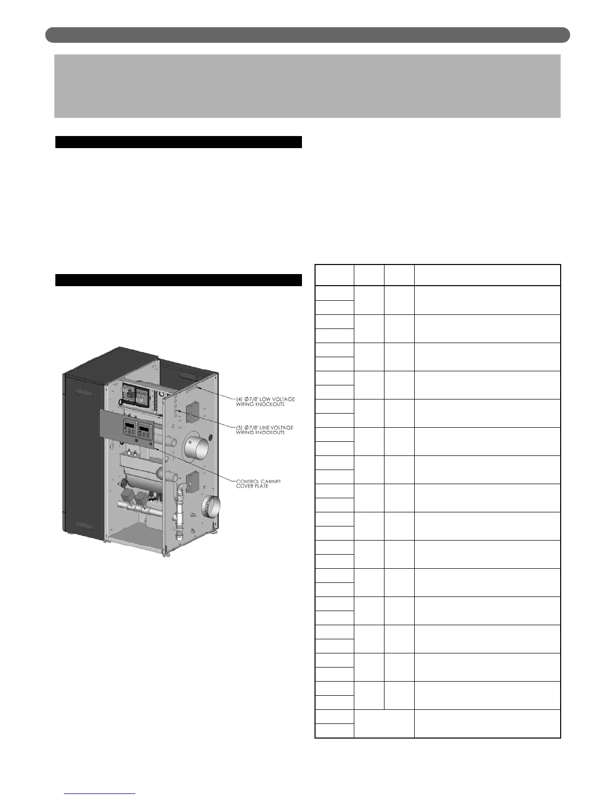
1. Electrical knockouts are provided on the rear panel of
the PF-850 and PF-1000 boiler to connect supply
wiring, circulator wiring, external controls, and/or
external sensors. Figure 7.1 shows these knockouts.
a. There are (5) 7/8" diameter knockouts for line
voltage connections such as supply wiring, circulator
wiring and low water cutoff (LWCO) wiring.
b. There are (4) 7/8" diameter knockouts for low
voltage connections such as outdoor sensors,
domestic hot water (DHW) tank sensors and
system sensors.
2. Electrical terminals are located behind the control
cabinet cover plate where the Burner LCD Displays
are mounted (See Figure 7.1).
a. The cover plate can be removed by removing the
single sheet metal screw on the lower center of the
panel. The top of the panels is supported by tabs
into the top of the cabinet enclosure.
b. The terminal strips can be removed by gently
pulling them away from the wired blocks. This
allows the installer to attach wires to the connector
before plugging the terminal strip into the
mounted block.
3. Figure 7.2 shows the customer connections for the
PF-850 and PF-1000 boilers. Table 7.1 lists the
terminal numbers with nominal voltage and detailed
descriptions of the connections.
ELECTRICAL CONNECTIONS & INTERNAL WIRING
7. ELECTRICAL CONNECTIONS &
INTERNAL WIRING
Figure 7.1: Electrical Terminal Access
Table 7.1: Terminal Description
Ter minal
Input/
Output
Voltage Description
1
Output 24 VAC
CH Thermostat, Boiler Output from Zone
Control Panel, or Zone Valve End
Switches.
2
3
Output 5 VDC
Outdoor Sensor (12 kW NTC Thermister) –
To be located outside the building (north
side in the shade).
4
5
Output 5 VDC
DHW Sensor (12 kW NTC Thermister) or
DHW Tank Thermostat.
6
7
Input/
Output
24
VDC
Master Communication Link – Wire to
terminals 9 & 10 on each Dependent
Boiler.
8
9
Input/
Output
24
VDC
Dependent Communication Link – Wire to
terminals 7 & 8 on Master Boiler and 9 &
10 on more Dependent Burners.
10
11
Output
24
VAC
Remove jumper to wire to external limit
controls such as Low Water Cutoff,
Damper or Power Vent Interlocks.
12
13
Output
5
VDC
System Sensor (12 kW NTC Thermister) –
To be located on the system supply header.
14
15 (-)
Input
0-10
VDC
External analog input for boiler target
setpoint temperature from Building
Management System (BMS).
16 (+)
17
Output
120
VAC
DHW Circulating Pump – Use this output
to power the domestic hot water (DHW)
circulator (Limited Priority).
18
19
Output
120
VAC
CH Circulating Pump – Use this output to
power the central heating (CH) circulator.
20
21
Output
120
VAC
GEN Circulating Pump – Use this output
to power the GEN (Boiler) circulator.
22
23
Input
120
VAC
120 VAC, 60 Hertz, 1 Phase supply from a
fused disconnect switch to power the boiler
controls and blowers.
24
25
Output
120
VAC
Line voltage output for probe-type low
water cutoff (LWCO) power.
26
27
Input
120
VAC
120 VAC, 60 Hertz, 1 Phase supply from a
fused disconnect switch to power the boiler
circulators.
28
29
N/A Ground Earth ground.
30
31
Dry Contacts
Alarm contacts (Operation may be
changed from the Installer Menu to allow
common venting of multiple boilers).
32