62
TROUBLESHOOTING
c. This will also occur if the wires are not properly
connected.
d. If there is a short at the DHW sensor terminals
and the DHW mode is set to Mode 1, the DHW
system will not operate. The display will blink to
indicate a warning error. Pressing the “Reset” key
will display the following error screen.
3. Flue Sensor Error:
a. If the control senses that the flue temperature does
not rise to above 50°F after ignition, and either the
supply water temperature rises above 120°F or the
return water temperature rises above 80°F, the control
will display “Flue Sensor Hold” and run at 1% Input.
b. If “Flue Sensor Hold” continues for an extended
period of time, the display will blink. Pressing the
“Reset” key will display the following error screen.
4. Cascade – System Sensor Error:
a. The system (header) sensor is mounted in the
supply (outlet) header on the PF-850 and PF-1000
boiler. If no system (header) sensor is connected
or if there is an open circuit, the display will blink
and the supply temperature on the front pixel
display will read 14°F.
b. If there is a short circuit in the system sensor
wiring, the display screen will blink and the supply
temperature on the front pixel display will read
244°F.
c. Under either of these conditions, the managing
burner will set the supply setpoints of both burners
to match the system setpoint. It will continue to
bring on and shut off boilers based on the
thermostat demand (terminals #1 and #2) and
the Boiler Start/Stop Delay Time.
5. No Comm. Error:
a. If the dependent burner is not communicating
with the managing burner and it is set as
“dependent burner” in the Installer Menu, the
screen will blink and the following message will be
displayed on the dependent burner LCD screen.
b. The burner will stay off until the condition is
corrected. The managing burner will operate
normally. However, if there is a NO COMM
CASCADE error, check the Installer Menu, under
Burner Options, on the managing burner to be
sure that it is set to “managing burner.
E. SPECIAL IGNITION/FLAME FAILURE
1. Depending on local codes the allowable number of
ignition attempts or flame failures may be different.
The “Installer Menu” may allow up to three ignition
attempts and three recycle attempts on flame failure.
In addition, it allows the installer to choose a “One
Hour Retry” option that can restart the boiler after
one hour of a lockout due to ignition or flame failure.
These values are set to the most restrictive from the
factory but can be changed at the boiler installation.
2. As a diagnostic tool, the P
UREFIRE
®
control logs the
flame signal four times during the last 2 seconds of
each ignition period. Each successive ignition will
overwrite the values from the previous ignition. This is
to aid in troubleshooting ignition errors. A flame
signal below 3.0 µA at the end of this period will result
in a failed ignition.
a. If the recorded flame signal values are low, 1.0 to
3.0 µA:
•
assure that the flame at ignition is visible
through the observation window
•
check that the position of the flame rod is
within 5/16" (9 mm) of the burner. Figure
10.10 shows the correct position of the flame
rod and ignition electrode
•
clean the flame rod with abrasive cloth
b. If the recorded flame signal values are below 1.0
µA:
•
check for an appropriate spark gap
•
check the flame rod for cracks in the ceramic
or corrosion bridging to metal
F. INTERLOCKS OPEN
1. An error message displaying, “E31 Interlocks Open”
may indicate several conditions:
a. Any interlock connected to terminals #11 & #12
on the boiler terminal blocks is open
b. The low or high gas pressure switch is tripped
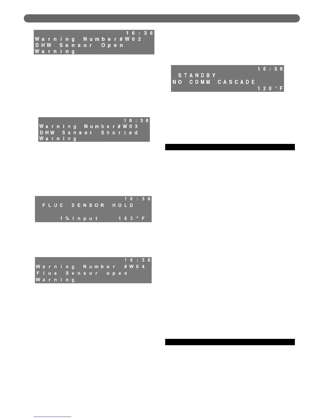
Figure 10.7: Warning – Flue Sensor Hold
Figure 10.8: Warning – Flue Sensor Open
Figure 10.9: Warning – No Communication Cascade
Figure 10.5: Warning – DHW Sensor Open
Figure 10.6: Warning – DHW Sensor Shorted