28
A. GENERAL
1. The disposal of all condensate into public sewage
systems is to be in accordance with local codes and
regulations. In the absence of such codes, follow these
instructions.
L'élimination de tout condensat dans les systèmes
d’évacuation publics des eaux usées doit s’effectuer
conformément aux codes et règlements en vigueur.
Si ces codes font défaut, suivre alors ces instructions.
2. Proper piping and removal of condensation from
combustion is critical to the operation of a condensing
appliance. Follow these instructions carefully to assure
that your P
UREFIRE
®
boiler operates correctly.
Pour le bon fonctionnement d’un appareil à
condensation, l'installation d'une tuyauterie adéquate
et la bonne évacuation de la condensation de la
combustion sont indispensables au fonctionnement
d’un appareil à condensation. Suivre attentivement
ces instructions pour assurer le fonctionnement
optimal de la chaudière P
UREFIRE
®
.
3. Depending on several factors, the condensate from
gas fired condensing appliances may have a pH value
as low as 2.5 (similar to cola soft drinks). Some local
codes require the use of neutralization equipment to
treat acidic condensate.
B. CONDENSATE SYSTEM
1. The condensate system for the PUREFIRE
®
PF-850 and
PF-1000 is designed to:
a. Prevent condensate from backing up into the heat
exchanger
b. Trap the condensate to prevent combustion gases
from escaping
c. Neutralize acidic condensate
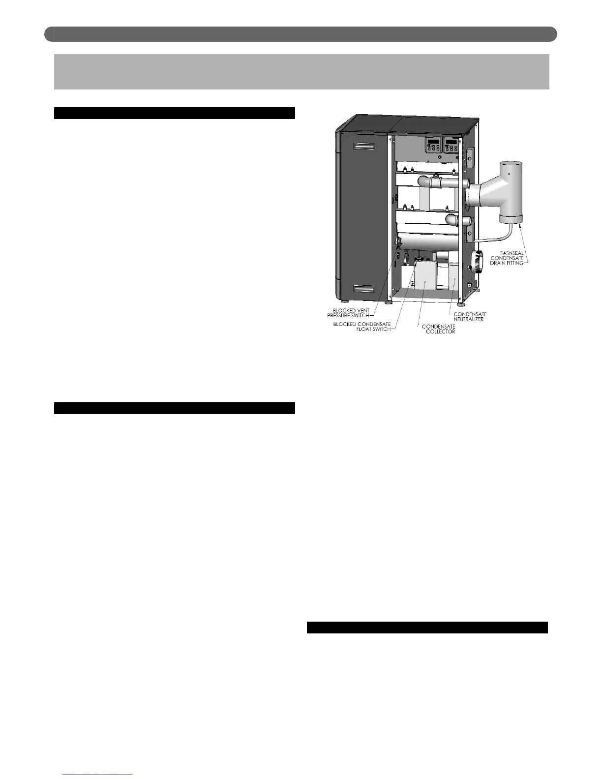
2. Figure 6.1 shows the components of the condensate
system.
a. Condensate Collector Container: This vessel is a
transparent plastic container designed to catch the
condensate separately from the heat exchanger
and from the exhaust venting system. This vessel
also acts as part of the trap to prevent combustion
gases from escaping. The container is fitted with a
blocked condensate float switch.
b. Blocked Condensate Float Switch: This switch will
cause a blocking error on the boiler control and
prevent the boiler from operating if the level of
condensate in the vessel becomes too high. High
condensate levels can occur as a result of a
blocked condensate drain or similar problem.
c. Condensate Neutralizer Container: This
transparent vessel completes the trap system. It is
also designed to hold the condensate neutralizing
media that is supplied with the boilers. Open the
screw cap and put neutralizing media into the
container. The amount of media consumed
depends on the acidity and amount of condensate
produced. This vessel should be checked
occasionally to determine if additional media is
required. Neutralizing media is available from your
PB Heat Distributor in 1 lb packages (#54159).
d. Blocked Vent Switch: A blocked vent switch is
connected to the condensate system to shut the
burner down in case of a vent blockage. The
switch will trip if the pressure in the combustion
chamber exceeds 4.5" w.c. (11 mbar) and will
prevent the boiler from continuing to operate with
the condensate trap emptied due to high pressure.
e. FasNSeal Condensate Drain Tee: The condensate
drain tee, included in a separate box inside the
crate, drains condensate to the trap and
neutralization system separately from the heat
exchanger. This prevents dirt and debris from the
venting system from entering the heat exchanger.
C. CONDENSATE DRAIN PIPING
1. Material: The condensate drain is to be piped using
PVC, polypropylene, or other material resistant to
acidic condensate. Do not use steel, brass, or
galvanized pipe for this purpose. The acidic condensate
will attack most metals and cause corrosion.
CONDENSATE TRAP & DRAIN SYSTEM
6. CONDENSATE TRAP & DRAIN SYSTEM
Figure 6.1: Condensate Trap System