17
b. The circulator should be sized based on gross
output of the boiler. Table 4.3 shows the Boiler
Output as reported to the Hydronics Institute
Section of AHRI.
c. The required flow is calculated based on the design
temperature difference from the return to the supply
of the boiler. For a PF-850 with a design temperature
difference of 20°F the calculation is as follows:
Output 816,000
Required Flow =
________
=
_________
= 81.6 GPM
D
T x 500 20 x 500
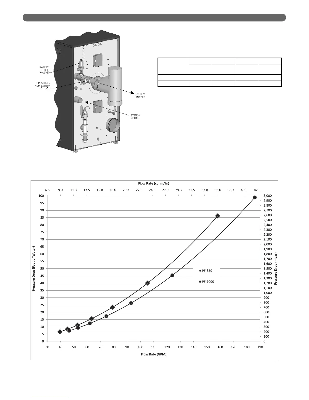
d. The boiler pressure drop for various flow rates
can be determined using Figure 4.3, the P
UREFIRE
®
PF-850/PF-1000 Sizing Graph.
e. Table 4.4 provides the flow rate and pressure drop
information that corresponds to various boiler
temperature rise values (DT). The pressure drop
shown is for the boiler only. If there is significant
system pressure drop in the piping, this should be
considered when specifying circulators.
WATER PIPING & CONTROLS
Table 4.3: Boiler Input and Output
Figure 4.3: PUREFIRE
®
Circulator Sizing Graph (General Pump – Primary/Secondary)
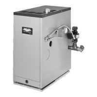
Figure 4.2: Relief Valve and Pressure/Temperature
Gauge Installation
PUREFIRE
®
Model
Boiler Input Boiler Output
Btu/hr kW Btu/hr kW
PF-850 850,000 249 817,700 240
PF-1000 1,000,000 293 966,000 283