56
b. The default address for each boiler is “0”
c. Selecting a boiler address of “1” assigns the boiler
as the master. Be sure that this is the boiler that is
connected to the system pumps and external
sensors.
d. Once a boiler is configured as the master boiler, a
menu containing all cascade options listed in Table
8.31 will be displayed. The remaining options are
intended to operate well with most boiler systems
using the default parameters. However, the
descriptions below allow the experienced installer
or service person to modify the operation of the
cascade system if improvements are warranted
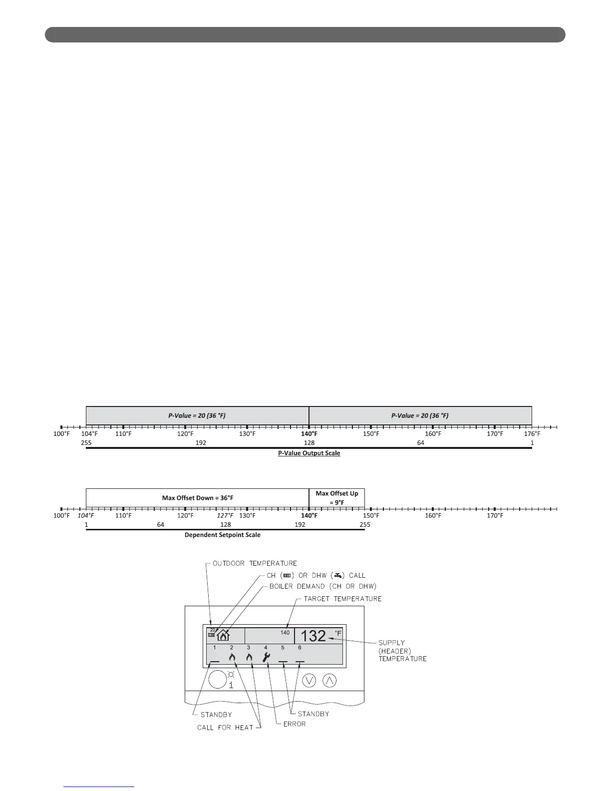
e) Figures 8.55 and 8.56 show how the P-Value, Max
Offset Up and Max Offset Down values affect the
dependent boiler setpoints.
i) The graphs illustrate the default values for the
control with a target temperature of 140°F.
ii) The control scales the actual supply
temperature to a 1-255 scale in the range
defined by the target temperature and the P-
Value. From Figure 8.55 we can see that if the
supply temperature is above 176°F the output
from the P-Value will be 1.
iii) Conversely, if the supply temperature is below
104°F the output from the P-Value will be 255.
At any point within the range, the P-Value will
be scaled. As an example, if the supply
temperature is at the 140°F setpoint the scaled
value will be 128.
f) Figure 8.56 illustrates the range defined by the Max
Offset Down and Max Offset Up parameters.
i) If the output from the P-Value is 1, the
dependent setpoint will be set to the minimum
value (104°F in this case).
ii) If the output from the P-Value is 255, the
dependent setpoint will be set to the maximum
value (149°F).
iii) From the previous example, the output value
from a supply temperature of 140°F yields a
value of 128. Transferring this value to the
dependent setpoint scale indicates that the
dependent boiler setpoints will be
approximately 127°F.
g) The I-Value determines how quickly the setpoint
changes. Larger values result in a slower response
time and smaller values decrease the response
time.
h) The Slew Rate limits the rate of change in
dependent boiler setpoint. In this case, a larger
value allows a faster change in setpoint while a
lower value limits the rate of change.
3) Cascade Display: When the master boiler has no
heat demand, there is no heat demand to the system.
Therefore, each boiler in the cascade will read
“CASCADE BOILER #” followed by its boiler address.
a) The master boiler will display, “CASCADE
BOILER #1”.
b) Pressing the down arrow will display the cascade
system information including the master supply
sensor temperature and the status of all boilers
with which it is communicating. See Figure 8.57
for the cascade status screen illustration.
Figure 8.55: P-Value Output
Figure 8.56: Dependent Setpoint
BOILER CONTROL: OPERATION
Figure 8:57: Cascade Status Screen