13 of 42
ISSUED: 03-08-07 SHEET #: 095-9264-1
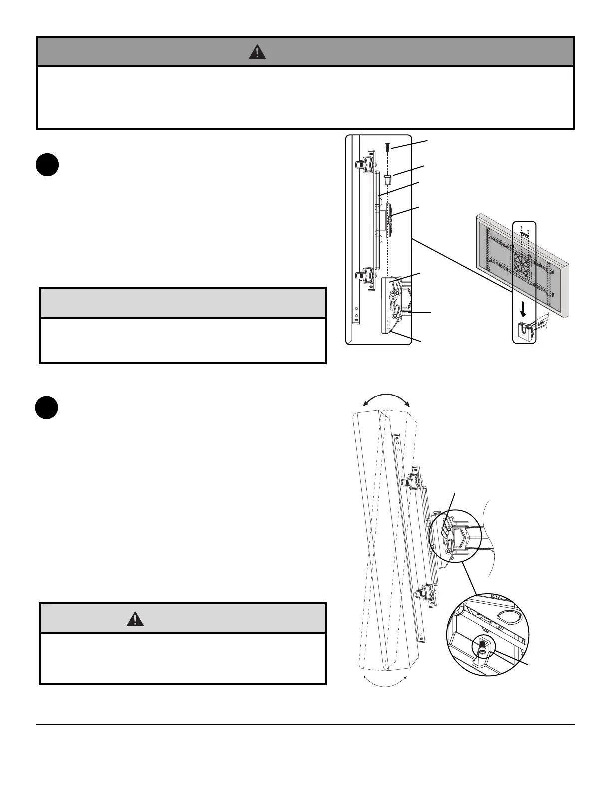
To attach screen to arm (A), insert the puck of adapter
plate into the tilt bracket slot as shown in figure 5.1.
Attach brake pad assembly as shown in Detail 5 so that
the brake pad is snug against the adapter plate. Adjust
roll position of adapter plate to level screen then lock puck
in place by tightening M5 x 25 mm screw on the
underside of tilt bracket using 4 mm allen wrench (N).
Tighten all (M5 x 20 mm, M5 x 25 mm) screws.
NOTE: To remove screen from arm (A), remove two
M5 x 20 mm screws and brake pad. Lift screen out of tilt
bracket.
5
Installing and Removing Flat Panel Screen
Adjustment of Flat Panel Screen
TENSION
KNOB
M5 X 25 MM
SCREW
BOTTOM
VIEW
6
• Do not lift more weight than you can handle. Use additional man power or mechanical lifting equipment to safely
handle placement of the screen.
• Failure to lock brake pad with two M5 x 20 mm screws and lock tilt bracket with M5 x 25 mm screw can cause
screen to come off mount if hit accidentally.
WARNING
fig. 5.1
DETAIL 5
ADAPTER PLATE
BRAKE PAD
TILT
BRACKET
M5 X 20 MM SCREW (QTY. 2)
M5 X 25 MM SCREW
A
PUCK
FOR PORTRAIT OR LANDSCAPE SCREEN ORIENTATION:
Remove two M5 x 20 mm screws and brake pad. Lift screen
out of tilt bracket. Rotate screen into portrait or landscape
position. Insert adapter plate puck into the tilt bracket slot as
shown in fig. 5.1. Attach brake pad to tilt bracket using two
M5 x 20 mm screws as shown in Detail 5. Tighten all
(M5 x 20 mm, M5 x 25 mm) screws.
TILT Adjustment: Adjust tension knob on side of mount to
desired tension to enable tilt adjustment and balance your
screen size and weight. Push or pull from top or bottom of
screen to adjust tilt as shown. The tilt can be adjusted to a
maximum of 10° forward or 5° backward. Retighten tension
knob.
ROLL Adjustment: Rotate screen either 5° clockwise or
counter-clockwise, level screen then tighten M5 x 25 mm
screw using 4 mm allen wrench (N) as shown in bottom view.
• Do not tighten screws with excessive force. Overtightening
can cause damage to mount. Tighten M5 x 20 mm screws
to 20 in. • lb (2.26 N.M.) maximum torque.
CAUTION
• Do not tighten screws with excessive force.
• Be careful not to pinch fingers when opening and closing
mount from the wall.
CAUTION