5. Determine if there are any existing devices on the
network that use a static IP address. Examples
might include printers, cameras, or other special
equipment.
6. Determine the static address range. The static
address range does not fall within the DHCP client
address range and does not conflict with any existing
devices that use a static IP address. For example,
if the DHCP client address range is 192.168.1.2
to 192.168.1.100, the space available for static IP
addressing would be 192.168.1.101 to 192.168.1.255.
- Record the static address range
(____.____.____.____ to ____.____.____.____).
Establishing a direct connection
The Ethernet control module is shipped with the Direct
Connect addressing mode enabled. When operating in
Direct Connect mode, the control module uses an integral
DHCP server to provide an IP address to your computer
and enables communications between your computer
and the control module.
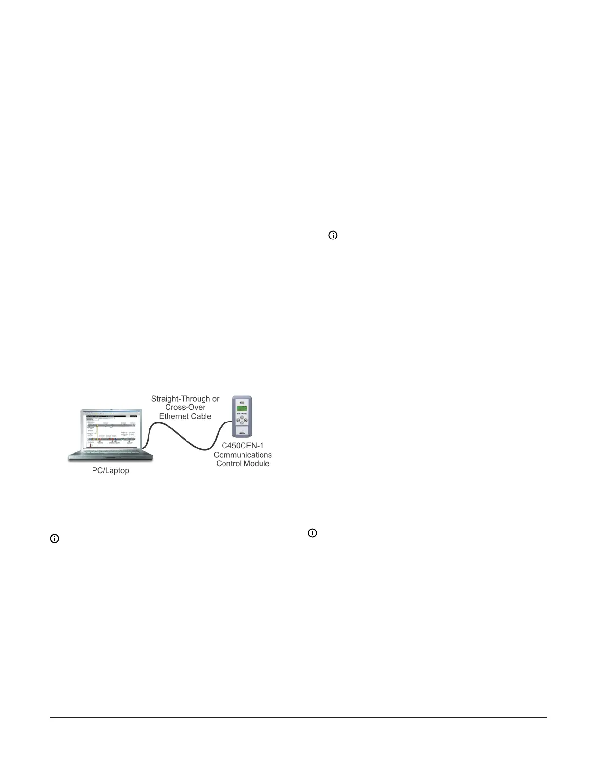
After you have established a direct connection between
your computer and the Ethernet control module (Figure
61), you can use a web browser on your computer to
browse to the Ethernet control module and set up the
Ethernet control module’s network configuration before
connecting it to an existing local network.
Figure 61: Direct connection between a laptop and a
System 450 Communications Control Module
You can also use the Direct Connection mode to connect
and browse to System 450 communications control
systems that are not permanently connected to a
network.
Note: The control module’s network settings, with
the exception of resetting the network configuration
to its default state, cannot be set up or changed
through the local user interface.
1. Start your computer and disable the wireless
networking feature (Wi-Fi) on the computer.
2. Connect an Ethernet cable (straight-through or
crossover) between your computer’s RJ-45 Ethernet
port and the Ethernet control module’s RJ-45
Ethernet port.
3. Connect power to the Ethernet control module.
Using the local UI, navigate to the Communications
Setup screen and verify that the address mode
is set to Direct (drct). If it is not, navigate to the
Reset Default Network Configuration screen and
restore the network configuration to its default
state. See Viewing network settings, setting the
remote network UI access lock, and resetting the
network settings for information on navigating to
and through the Communications Setup screen.
4. Open the Windows
®
Internet Explorer
®
web
browser on your computer. The Internet Explorer
browser at version 9 or later is recommended and
supported.
5. Type the IP address 169.254.1.1 into the browser’s
address bar and press Enter. The System 450
Overview and Login page should appear (Figure 63).
Note: If the Ethernet control module does
not respond, close the browser, wait for 1 to 2
minutes, and try again. It may take some time
for the control module to assign an IP address
to your computer. If the control module still
does not respond, you may need to turn the
power off and on.
6. Enter the System 450 web server username and
password to log in. On your initial login to the
communications control module’s web UI, enter
System450User1 into the WebUserName field and
Wx9jc3 into the Web Password field.
After you log in, you can set up your control system
parameters and configure the Ethernet control module
with a static IP address for connection to a local network.
Refer to the System 450 Series Control Modules with
Communications Technical Bulletin (LIT-12011826) for
information on accessing Ethernet control systems from
the Internet.
Setting up a Static IP address
To configure your Ethernet control module for a local
network using a static IP address, you must determine
the default gateway (router) address and subnet mask on
your local network and a static IP address for the control
module.
Note: Your network administrator may be able
to provide most or all of this network setup
information.
1. See Establishing a direct connection for instructions
about how to connect a computer directly to the
Ethernet control. Log in to the System 450 web UI
and go to the Network Configuration page (Figure
68).
2. In the IP Address section on the Network
Configuration page, click the Static IP Address option
in the IP Address section. Use a value from the static
address range determined in Step 6 of Setting up
Ethernet communications.
System 450 Series Control Module with Ethernet Communications Installation Guide 23
 Loading...

