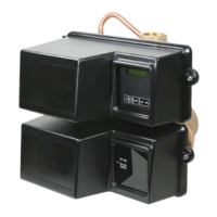
NETWORK/COMMUNICATION CABLES
AND CONNECTIONS
Use either a CAT3 or CAT5 Network/Communication cable.
Connect the network/communication cable first before
programming.
The maximum cable length between timers is 100 feet.
Connect each unit together from one communication port to
the next communication port. It does not matter which one
goes to the next one.
Communication Ports
Ground
Lock
Regen
Figure 2 NXT Circuit Board
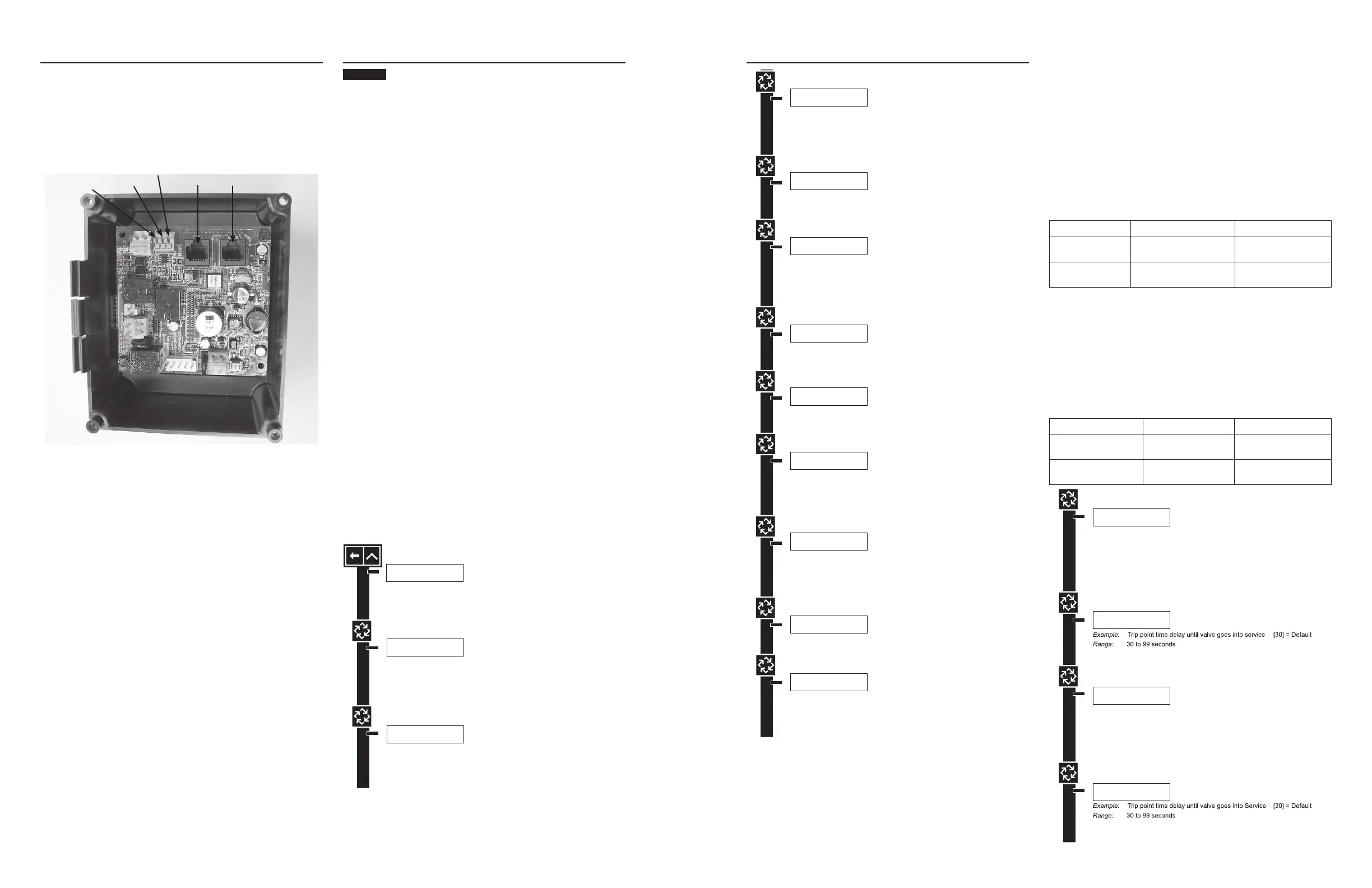
MASTER PROGRAMMING MODE
FLOW CHART
Before entering Master Programming, please
contact your local professional water dealer.
NOTE: Depending on current option settings, some displays
cannot be viewed or set.
Entering Master Programming Mode
1. Press and hold the Shift and Up buttons for 5 seconds.
Press the Extra Cycle button once per display until all
displays are viewed and Normal Display is resumed. Option
setting displays may be changed as required by pressing
either Up or Down button. Use the Shift button to move one
space to the left.
2. Depending on current valve programming, certain displays
may not be viewed or set.
NOTE: If the "D" button is pressed while in master
programming, no changes will be saved.
Exiting Master Programming Mode
1. Press the Extra Cycle button once per display until all
are viewed. Master Programming Mode is exited and the
normal display screen appears.
2. To exit the Master Programming Mode without saving
changes, press the Diagnostic button.
NOTE: If no keypad activity is made for 5 minutes while in
the Master Programming Mode, or if there is a power
failure, no changes will be saved, and the unit will go
back to the main display screen.
Resets
Soft Reset: Press and hold the Up and Down buttons for 25
seconds until 12:00PM (or 12:00HR) appears. This resets all
parameters except for the flow meter totalizer volume.
Master Reset: Hold the Extra Cycle button while powering up
the unit. This resets all of the parameters in the unit. Check
and verify the choices selected in Master Programming Mode.
NOTE: If the "D" button is pressed while in master
programming, no changes will be saved.
VALV E ADDRESS:
#2
Options: Valve Address #1 (First Control Valve)
Valve Address #2 (Second Control Valve) (Default)
Valve Address #3 (Third Control Valve)
Valve Address #4 (Fourth Control Valve)
SYSTEM TYPE: 4
SINGLE UNIT
Options: System 4 (single unit)
System 5 (2-4 units) Parallel Interlock
System 6 (2-4 units) Parallel Series Regeneration
System 7 (2 units) Alternating
System 9 (2-4 units) Alternating
System 14 (2-4 units) Demand Recall
Example:
System Type 4, Single Unit
Example:
Valve Address #2 (Second Control Valve) (Default)
Example:
U.S. Gallons (Default)
SELECT LANGUAGE:
ENGLISH
Options: English
Espanol
Portugues
Deutsch
Francais
Example:
English
VALV E TYPE:
2750
Options: 2750 (Default)
2815
2850
2900
3150
3900
Stager - Notch Cam
Example:
2750 (Default)
REGEN TYPE:
TIME CLK DELAYED
Options: Time Clock Delayed (System 4 Only) (Default)
Meter Immediate (All System Types)
Meter Delayed Fixed Reserve (Systems 4 & 6 Only)
Example:
Time Clock Delayed (Default)
REGENERANT FLOW:
DOWNFLOW
Options: Downflow (Default)
Up Flow
UF Fill First
Example:
Downflow (Default)
REMOTE SIGNAL
START: 00:06:00
Options: Off (Default)
00:00:00 (Hours:Minutes:Seconds)
Range: 1 second to 99 minutes (1 hour, 39 minutes)
NOTE: This display will not be viewed in System 4
Example:
00:06:00
(Hours:Minutes:Seconds)
NOTE: This screen will not display for System Type 4.
SYSTEM SIZE:
2 VALVES
Options: 2 Valves in the System (Default)
3 Valves in the System
4 Valves in the System
Example:
2 Valves in the System (Default)
Range: 2 to 4 Valves in the System
NOTE: This screen will not display for System Type 4.
DISPLAY FORMAT:
US-GALLONS
Options: U.S. - Gallons (Default)
Eu Metric - Liters (Metric)
NOTE: In European Units - Liters (Metric) mode, the display will be in
24-hour time.
NOTE: In U.S. - Gallons mode, the display will be in 12-hour time.
UNIT CAPACITY:
00000000 GRAINS
Options: Grains (in U.S. Format) (Default)
Grams (in Metric Format)
Example:
Grains (Default)
NOTE: Use the Shift button to move to the left.
Range: 1 to 9,900,000 Grain Capacity in U.S. Format
1 to 198,000 grams CaCO3 Capacity in Metric Format
Example:
00% (Default)
CAPACITY SAFETY
FACTOR: 00%
Range: 0 to 50%
NOTE: Use the Shift button to move to the left.
FEED WATER
HARDNESS: 15 GPG
Range: 1 to 199 Grains/Gallon (U.S. Format)
20 to 1,999 miligrams CaCO3/L (Metric Format)
Example:
15 GPG (U.S. Format) (Default)
NOTE: Use the Shift button to move to the left.
NOTE: This screen will only display on the lead unit for System Types 6 & 7.
For all other System Types, it will display for all units.
TRIP POINT 1:
000 gpm
NOTE: Display will not appear unless timer is programmed as valve position
#1. Use the Shift button to change each decimal position.
REGENERATION DAY
OVERRIDE:OFF
Example:
Off (Default)
On (Default for time clock)
REGENERATION DAY
OVERRIDE:01 DAYS
Options: Off (Default for meter) or On
Example:
1 Day
Range: 1 to 99 Days
REGENERATION
TIME: 02:00AM
Example:
2:00 A.M. (Default)
Options: A.M. (U.S. Format)
HR (Metric Format)
NOTE: Regeneration time will not appear unless Regeneration Day Override
is on.
CYCLE 1 00:00:00
BACK WASH
Example:
Cycle 1 in Back Wash Mode
Options: Regeneration Cycle Step #1
Regeneration Cycle Step #2
Regeneration Cycle Step #3
Regeneration Cycle Step #4
Regeneration Cycle Step #5
NOTE: Please refer to the “Regenerant Flow Default Cycle Steps & Times”
in the Master Programming Mode section of the manual.
NOTE: If Stager is chosen for Valve Type, the Regeneration Cycle Step
description will not display.
AUXILIARY RELAY:
DISABLED
Example:
Auxiliary Relay is Disabled
Options: Enabled
Disabled (Default)
AUX RELAY OUTPUT
START 1 00:00:00
Example:
Auxiliary Relay Output in Start 1 at
0 hours, 0 minutes, & 0 seconds
Range: 00:00:00 to 18:00:00
NOTE: Only displayed if Auxiliary Relay is enabled in previous screen.
Auxiliary Relay will only display if Chemical Pump is OFF for System
Types 6 & 7.
AUX RELAY OUTPUT
END 1 00:00:00
Example:
Auxiliary Relay Output in End 1 at
0 hours, 0 minutes, & 0 seconds
Range: 00:00:00 to 18:00:00
CHEMICAL PUMP:
DISABLED
Example:
Chemical Pump is Disabled
Options: Enabled
Disabled (Default)
NOTE: This screen will only display on the lead unit for System Types 6 & 7.
For all other System Types, it will display for all units.
CPO AUX RELAY
VOLUME: 000 g
Example:
Energize Chemical Pump Relay Every 50 Gallons
Energize Chemical Pump Relay Every 200 L
Range: 1 to 999 gallons in U.S. Format
1 to 9999 L in Metric Format
NOTE: Only displayed on units that physically have a meter (Lead always has
a meter). Only shown if Auxiliary Relay is disabled on System Types 6 & 7.
CPO AUX RELAY
TIME: 00:00:00
Example:
Each Time the Chemical Pump Relay is on, Run
for 30 Seconds (00:00:30)
Range: 00:00:00 to 02:00:00
FLOW METER:
1.0 PADDLE
Example:
1.0 Paddle Flow Meter
Options: 1.0 Paddle (Fleck)
1.0 Turbine (Fleck)
1.5 Paddle (Fleck)
1.5 Turbine (Fleck)
2.0 Paddle (Fleck)
3.0 Paddle (Fleck)
Generic (Non-Fleck)
NOTES: Default flow meter type is based on the valve type. This screen will
only display on the lead unit for System Types 6 & 7. All other system types
it will display for all units.
MAXIMUM FLOW
RATE: 0000 gpm
Example:
Maximum Flow Rate of 0 gpm
Range: 20 - 2000 gpm (U.S. Format)
20 - 2000 L (Metric Format)
NOTE: Only displayed if “Generic” is chosen for the flow meter.
Range: 1 - 255 Gallons (U.S. Format)
1 - 255L (Metric Format)
Pulses: 1 - 255
Options: Gallons (U.S. Format)
Liters (Metric Format)
ADD 01 GALLONS
EVERY 001 PULSES
Example:
Add 1 Gallon for Each Pulse in U.S. Format
NOTE: Only displayed if “Generic” is chosen for the flow meter.
PROGRAMMING UNIT
PLEASE WAIT...
Example:
Master Programming Mode is Exiting
NOTE: Display will not appear unless timer is programmed as valve position
#1. Use the Shift button to move one space to the left.
TRIP DELAY 1:
30 SECONDS
NOTE: Display will not appear unless timer is programmed as valve position
#1. System size must be 3 or 4 to appear. Use the Shift button to move one
space to the left.
TRIP DELAY 2:
30 SECONDS
NOTE: Display will not appear unless timer is programmed as valve position
#1. System size must be 3 or 4 to appear. Use the Shift button to move one
space to the left.
TRIP POINT 2:
gpm
NOTE: Display will not appear unless timer is programmed as valve position
#1. System size must be 4 to appear. Use the Shift button to move one
space to the left.
TRIP POINT 3:
gpm
NOTE: Display will not appear unless timer is programmed as valve position
#1. System size must be 4 to appear. Use the Shift button to move one
space to the left.
TRIP DELAY 3:
30 SECONDS
Examples: Default will need to be changed before next step [000] = (Default)
Brings 2nd valve In Service after 125 gpm [125]
Brings 2nd valve In Service after 400 lpm [400]
Range: 1 to 997 gpm (U.S. Format)
0.01 to 3997 lpm (Metric Format)
Examples: Brings 3rd valve In Service after 250 gpm [250]
Brings 3rd valve In Service after 900 lpm [900]
Range: Trip Point 1 + 1 to 998 gpm (U.S. Format)
Trip Point 1 + 1 to 3998 lpm (Metric Format)
Examples: Brings 4th valve In Service after 350 gpm [350]
Brings 4th valve In Service after 1300 lpm [1300]
Range: Trip Point 2 + 1 to 999 gpm (U.S. Format)
Trip Point 2 + 1 to 3999 lpm (Metric Format)
MASTER PROGRAMMING MODE FLOW
CHART continued
VALV E ADDRESS:
#2
Options: Valve Address #1 (First Control Valve)
Valve Address #2 (Second Control Valve) (Default)
Valve Address #3 (Third Control Valve)
Valve Address #4 (Fourth Control Valve)
SYSTEM TYPE: 4
SINGLE UNIT
Options: System 4 (single unit)
System 5 (2-4 units) Parallel Interlock
System 6 (2-4 units) Parallel Series Regeneration
System 7 (2 units) Alternating
System 9 (2-4 units) Alternating
System 14 (2-4 units) Demand Recall
Example:
System Type 4, Single Unit
Example:
Valve Address #2 (Second Control Valve) (Default)
Example:
U.S. Gallons (Default)
SELECT LANGUAGE:
ENGLISH
Options: English
Espanol
Portugues
Deutsch
Francais
Example:
English
VALV E TYPE:
2750
Options: 2750 (Default)
2815
2850
2900
3150
3900
Stager - Notch Cam
Example:
2750 (Default)
REGEN TYPE:
TIME CLK DELAYED
Options: Time Clock Delayed (System 4 Only) (Default)
Meter Immediate (All System Types)
Meter Delayed Fixed Reserve (Systems 4 & 6 Only)
Example:
Time Clock Delayed (Default)
REGENERANT FLOW:
DOWNFLOW
Options: Downflow (Default)
Up Flow
UF Fill First
Example:
Downflow (Default)
REMOTE SIGNAL
START: 00:06:00
Options: Off (Default)
00:00:00 (Hours:Minutes:Seconds)
Range: 1 second to 99 minutes (1 hour, 39 minutes)
NOTE: This display will not be viewed in System 4
Example:
00:06:00
(Hours:Minutes:Seconds)
NOTE: This screen will not display for System Type 4.
SYSTEM SIZE:
2 VALVES
Options: 2 Valves in the System (Default)
3 Valves in the System
4 Valves in the System
Example:
2 Valves in the System (Default)
Range: 2 to 4 Valves in the System
NOTE: This screen will not display for System Type 4.
DISPLAY FORMAT:
US-GALLONS
Options: U.S. - Gallons (Default)
Eu Metric - Liters (Metric)
NOTE: In European Units - Liters (Metric) mode, the display will be in
24-hour time.
NOTE: In U.S. - Gallons mode, the display will be in 12-hour time.
UNIT CAPACITY:
00000000 GRAINS
Options: Grains (in U.S. Format) (Default)
Grams (in Metric Format)
Example:
Grains (Default)
NOTE: Use the Shift button to move to the left.
Range: 1 to 9,900,000 Grain Capacity in U.S. Format
1 to 198,000 grams CaCO3 Capacity in Metric Format
Example:
00% (Default)
CAPACITY SAFETY
FACTOR: 00%
Range: 0 to 50%
NOTE: Use the Shift button to move to the left.
FEED WATER
HARDNESS: 15 GPG
Range: 1 to 199 Grains/Gallon (U.S. Format)
20 to 1,999 miligrams CaCO3/L (Metric Format)
Example:
15 GPG (U.S. Format) (Default)
NOTE: Use the Shift button to move to the left.
NOTE: This screen will only display on the lead unit for System Types 6 & 7.
For all other System Types, it will display for all units.
TRIP POINT 1:
000 gpm
NOTE: Display will not appear unless timer is programmed as valve position
#1. Use the Shift button to change each decimal position.
REGENERATION DAY
OVERRIDE:OFF
Example:
Off (Default)
On (Default for time clock)
REGENERATION DAY
OVERRIDE:01 DAYS
Options: Off (Default for meter) or On
Example:
1 Day
Range: 1 to 99 Days
REGENERATION
TIME: 02:00AM
Example:
2:00 A.M. (Default)
Options: A.M. (U.S. Format)
HR (Metric Format)
NOTE: Regeneration time will not appear unless Regeneration Day Override
is on.
CYCLE 1 00:00:00
BACK WASH
Example:
Cycle 1 in Back Wash Mode
Options: Regeneration Cycle Step #1
Regeneration Cycle Step #2
Regeneration Cycle Step #3
Regeneration Cycle Step #4
Regeneration Cycle Step #5
NOTE: Please refer to the “Regenerant Flow Default Cycle Steps & Times”
in the Master Programming Mode section of the manual.
NOTE: If Stager is chosen for Valve Type, the Regeneration Cycle Step
description will not display.
AUXILIARY RELAY:
DISABLED
Example:
Auxiliary Relay is Disabled
Options: Enabled
Disabled (Default)
AUX RELAY OUTPUT
START 1 00:00:00
Example:
Auxiliary Relay Output in Start 1 at
0 hours, 0 minutes, & 0 seconds
Range: 00:00:00 to 18:00:00
NOTE: Only displayed if Auxiliary Relay is enabled in previous screen.
Auxiliary Relay will only display if Chemical Pump is OFF for System
Types 6 & 7.
AUX RELAY OUTPUT
END 1 00:00:00
Example:
Auxiliary Relay Output in End 1 at
0 hours, 0 minutes, & 0 seconds
Range: 00:00:00 to 18:00:00
CHEMICAL PUMP:
DISABLED
Example:
Chemical Pump is Disabled
Options: Enabled
Disabled (Default)
NOTE: This screen will only display on the lead unit for System Types 6 & 7.
For all other System Types, it will display for all units.
CPO AUX RELAY
VOLUME: 000 g
Example:
Energize Chemical Pump Relay Every 50 Gallons
Energize Chemical Pump Relay Every 200 L
Range: 1 to 999 gallons in U.S. Format
1 to 9999 L in Metric Format
NOTE: Only displayed on units that physically have a meter (Lead always has
a meter). Only shown if Auxiliary Relay is disabled on System Types 6 & 7.
CPO AUX RELAY
TIME: 00:00:00
Example:
Each Time the Chemical Pump Relay is on, Run
for 30 Seconds (00:00:30)
Range: 00:00:00 to 02:00:00
FLOW METER:
1.0 PADDLE
Example:
1.0 Paddle Flow Meter
Options: 1.0 Paddle (Fleck)
1.0 Turbine (Fleck)
1.5 Paddle (Fleck)
1.5 Turbine (Fleck)
2.0 Paddle (Fleck)
3.0 Paddle (Fleck)
Generic (Non-Fleck)
NOTES: Default flow meter type is based on the valve type. This screen will
only display on the lead unit for System Types 6 & 7. All other system types
it will display for all units.
MAXIMUM FLOW
RATE: 0000 gpm
Example:
Maximum Flow Rate of 0 gpm
Range: 20 - 2000 gpm (U.S. Format)
20 - 2000 L (Metric Format)
NOTE: Only displayed if “Generic” is chosen for the flow meter.
Range: 1 - 255 Gallons (U.S. Format)
1 - 255L (Metric Format)
Pulses: 1 - 255
Options: Gallons (U.S. Format)
Liters (Metric Format)
ADD 01 GALLONS
EVERY 001 PULSES
Example:
Add 1 Gallon for Each Pulse in U.S. Format
NOTE: Only displayed if “Generic” is chosen for the flow meter.
PROGRAMMING UNIT
PLEASE WAIT...
Example:
Master Programming Mode is Exiting
NOTE: Display will not appear unless timer is programmed as valve position
#1. Use the Shift button to move one space to the left.
TRIP DELAY 1:
30 SECONDS
NOTE: Display will not appear unless timer is programmed as valve position
#1. System size must be 3 or 4 to appear. Use the Shift button to move one
TRIP DELAY 2:
30 SECONDS
NOTE: Display will not appear unless timer is programmed as valve position
#1. System size must be 3 or 4 to appear. Use the Shift button to move one
space to the left.
TRIP POINT 2:
gpm
NOTE: Display will not appear unless timer is programmed as valve position
#1. System size must be 4 to appear. Use the Shift button to move one
space to the left.
TRIP POINT 3:
gpm
NOTE: Display will not appear unless timer is programmed as valve position
#1. System size must be 4 to appear. Use the Shift button to move one
space to the left.
TRIP DELAY 3:
30 SECONDS
Examples: Default will need to be changed before next step [000] = (Default)
Brings 2nd valve In Service after 125 gpm [125]
Brings 2nd valve In Service after 400 lpm [400]
Range: 1 to 997 gpm (U.S. Format)
0.01 to 3997 lpm (Metric Format)
Examples: Brings 3rd valve In Service after 250 gpm [250]
Brings 3rd valve In Service after 900 lpm [900]
Range: Trip Point 1 + 1 to 998 gpm (U.S. Format)
Trip Point 1 + 1 to 3998 lpm (Metric Format)
Examples: Brings 4th valve In Service after 350 gpm [350]
Brings 4th valve In Service after 1300 lpm [1300]
Range: Trip Point 2 + 1 to 999 gpm (U.S. Format)
Trip Point 2 + 1 to 3999 lpm (Metric Format)
Trip Points 1, 2, and 3 (System 14 only)
This program step selects up to three Trip Points programmed
on the master timer only (Valve Address #1).
The actual required number of Trip Points in a system is one
less than the number of valves in the system.
Trip Point 1 represents the system flow rate at which a second
valve will be brought In Service or Standby.
Trip Point 2 represents the system flow rate at which a third
valve will be brought In Service or Standby.
Trip Point 3 represents the system flow rate at which a fourth
valve will be brought In Service or Standby.
Trip Point 1 Trip Point 2 Trip Point 3
Range:
1 – 997 GPM
U.S.: Value of Trip Point
1 plus 1 to 998
U.S.: Trip Point 2 plus
1 to 999
Range:
0001 – 3997 Lpm
Metric: Value of Trip
Point 1 plus 1 - 3998
Metric: Trip Point 2
plus 1 - 3999
Trip Delays 1, 2, and 3 (System 14 only)
This program step selects each Trip Delay time that is
addressed with each Trip Point and will be programmed on
the Master timer only (Valve Address #1). The Trip Delay time
represents a minimum amount of time the system flow rate
is required to be equal or greater than the Trip Points to bring
a unit In Service. It also is the minimum amount of time the
system flow rate is required to be less than the Trip Points to
remove a unit from In Service to Standby.
Trip Delay 1 Trip Delay 2 Trip Delay 3
Default: 30 Seconds
Range:
30 - 99 Seconds
Range:
30 - 99 Seconds
Range:
30 - 99 Seconds
8 • Fleck 3200 NXT Fleck 3200 NXT • 9
 Loading...