SYSTEM DEFINITIONS
System
Number
System
Description
# of
Tanks/
Controls
Type Operation Discussion
4 Single Unit 1 Time Clock: No Meter
Immediate: One Meter
Delayed: One Meter
Remote Signal Start: No Meter
Single tank configuration.
5 Interlocked 2, 3, or 4 Immediate: All Meters
Remote Signal Start: No Meter
All tanks in parallel supplying treated water. Each unit in the system
will have its own flow meter/sensor input. The control will delay the
start of Regeneration if another unit is already in Regeneration. Once
that unit has completed a Regeneration cycle, and has returned to
Service,the unit with longest regeneration queue time will begin
Regeneration. No more than one unit will be in Regeneration at a time.
6 Series
Regeneration
2, 3, or 4 Immediate: One Meter
Delayed: One Meter
Remote Signal Start: No Meter
All tanks in parallel supplying treated water. Only #1 control will
monitor flow meter/sensor input. When a regeneration is required
for the system, it will regenerate valve address #1 first, immediately
followed by #2, then #3, then #4 if installed. No more than one unit
will be in Regeneration at a time.
7 Twin
Alternating
2 Immediate: One Meter
Remote Signal Start: No Meter
One tank online supplying treated water, one tank in Standby. Only
#1 control will monitor its flow meter/sensor input. Regeneration of
a unit will begin after the other control has left Standby and returned
to Service. When the Regeneration cycle is complete, the regenerated
unit will enter Standby. Standby on each tank is controlled by the lower
drive output terminals on the NXT circuit board.
9 Multiple Tank
Alternating
2, 3, or 4 Immediate: All Meters
Remote Signal Start: No Meter
One, two, or three tanks online supplying treated water, one tank in
Standby. Meter/sensor input is required on each tank. Regeneration of
a unit will begin after the other control has left Standby and returned
to Service. When the Regeneration cycle is complete, the regenerated
unit will enter Standby. Standby on each tank is controlled by the lower
drive output terminals on the NXT circuit board.
14 Demand
Recall
2, 3, or 4 Immediate: All Meters Meter input is required on each tank. Unit #1 will begin In Service with
#2, #3, and #4 (if installed) will begin in Standby. At least one unit is
In Service at all times. When flow rate to the Primary Service Unit
increases to a user specified rate, the next unit in sequence will move
from Standby to Service. As the flow rate falls below the user specified
rate subsequent tanks will return to Standby. When the Primary
Service Unit regenerates, the next unit in sequence will become
the new Primary Service Unit. As each units capacity is reached the
controller will initiate a Regeneration of that unit. Depending on the
number of units in the system, and flow rate demand the regenerated
unit will then be placed either into Standby or Service. Only one unit
will be in Regeneration at a time.
SYSTEM OPERATION IN SERVICE
(SYSTEM 14-DEMAND RECALL)
The system operates as part of a multi-valve regeneration
system.
Each valve in the system will have an active flow meter input,
even in Standby.
The number of valves in service depends on the flow rate.
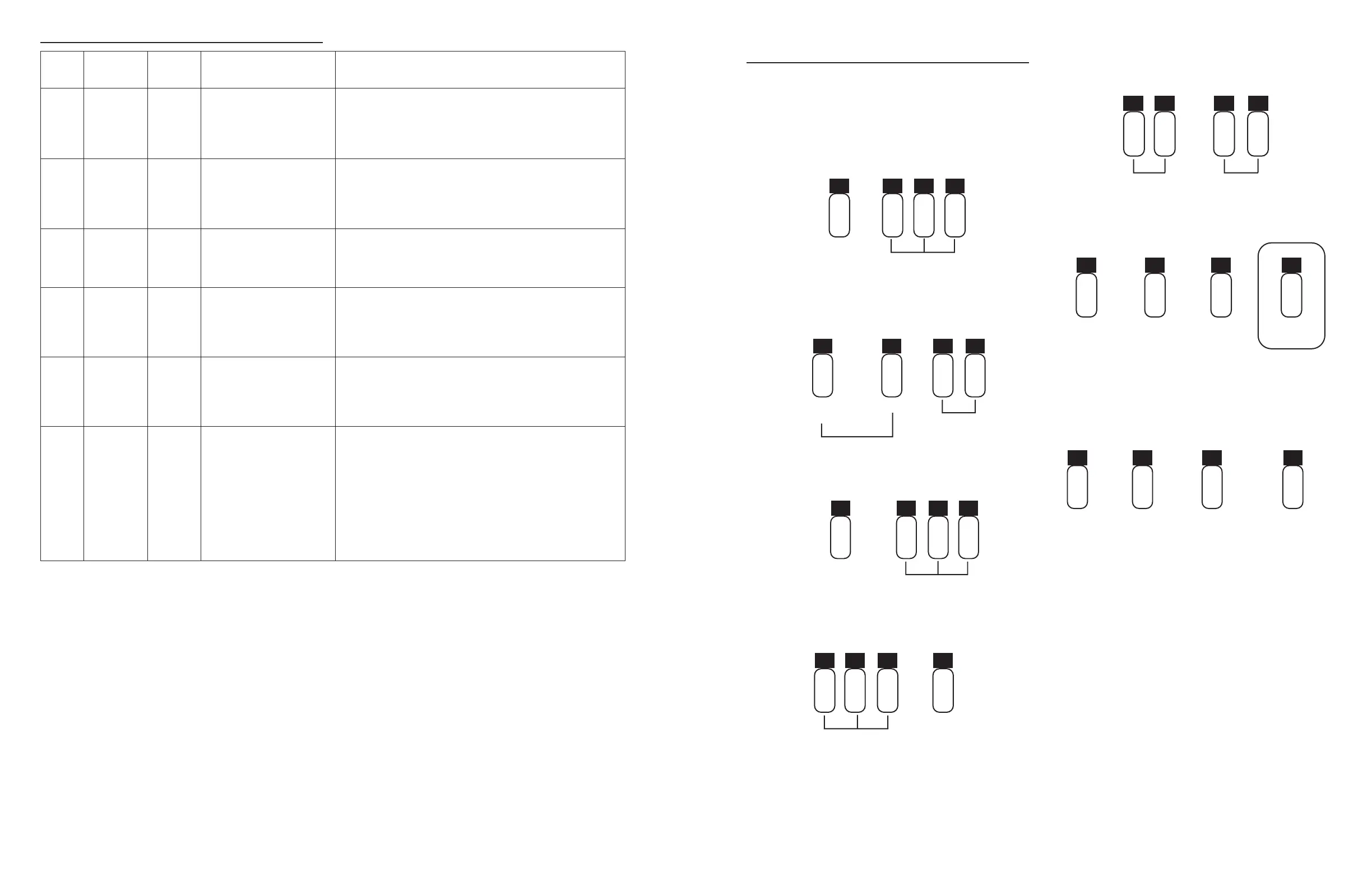
Examples of a Four-Unit System:
1. One Valve is in service at all times (the "primary valve").
In Service
(Primary Tank)
Standby
123 4
2. The total flow rate to the primary valve increased past
the first trip point programmed rate. The flow stayed past
the trip point delayed time. The next valve (least volume
remaining) changes from Standby to In Service. This valve
then splits the total flow between two meters.
In Service
1234
Standby
First Trip Point
(Primary Valve)
Total Flow Split
Between Two Meters
3. The flow rate demand decreased below the first trip point.
The valve returns to Standby.
Standby
Flow Rate Demand
Below First Trip Point
(Primary Valve)
123 4
4. Total flow rate demand increased past a second trip point
programmed rate. The second and third valve (least volume
remaining) changes from Standby to In Service. The total
flow is split between the three meters.
Standby
Flow Split Between
Three Meters
12 3 4
5. The third valves returns to stand by as demand decreases
past the second trip point.
Standby
Flow Split Between
Two Meters
1 2 34
6. Valves return to stand by due to decreased total flow rate
and trip points programmed. The valve with the most
remaining volume will be the first to go into Standby.
Full Capacity
4th in Standby
(Primary Valve)
3/4 Capacity
3rd in Standby
1 2
1/2 Capacity
2nd in Standby
1/4 Capacity
1st in Standby
7. The primary valve regenerates. The next valve with the least
remaining volume becomes the new primary valve. The
valve with the next least volume remaining will be the first
trip point programmed rate. Valves continue operating in
this order.
Full Capacity
3/4 Capacity
3rd in Standby
1 2
1/2 Capacity
First Trip Point
1/4 Capacity
New Primary Tank
System Operation in Regeneration:
If two valves are In Service and both reach
Volume Remaining = 0, the other two valves will shift from
Standby to In Service. The lead valve with
Volume Remaining = 0 will start regeneration. The second valve
with Volume Remaining = 0 will enter Standby. If flow increases
past the trip point a third valve needs to enter In Service. The
valve in Standby with Volume Remaining = 0 will shift into
In Service to maintain a steady flow. Operating for extended
periods in this mode may degrade the water quality.
4 • Fleck 3200 NXT Fleck 3200 NXT • 5