TIMER OPERATION
Setting the Time of Day
NOTE: Set Time of Day on the Lead Unit (#1) and the rest of
the units in the system will update the Time of Day
within 10 seconds.
1. Press and hold the Up or Down button for 2 seconds.
2. Press the Shift button to select the digit you want to modify.
3. Press the Up or Down buttons to adjust the valve.
4. Press the Extra Cycle button to return to the normal display
screen, or wait for a 5 second timeout.
NOTE: The "D" button (Diagnostic) can be pressed to exit
without saving.
Manually Initiating a Regeneration
1. When timer is In Service or Stand By, press the Extra Cycle
button for 5 seconds on the main screen.
2. The timer advances to Regeneration Cycle Step #1, and
begins programmed time count down.
3. Press the Extra Cycle button once to advance valve to
Regeneration Cycle Step #2 (if active).
4. Press the Extra Cycle button once to advance valve to
Regeneration Cycle Step #3 (if active).
5. Press the Extra Cycle button once to advance valve to
Regeneration Cycle Step #4 (if active).
6. Press the Extra Cycle button once to advance valve to
Regeneration Cycle Step #5 (if active).
7. Press the Extra Cycle button once more to advance the
valve back to In Service.
NOTE: A manually initiated or queued regeneration can
be cleared by pressing the Extra Cycle button for
less than 5 seconds. A system queued regeneration
can only be cleared by stepping through a manual
regeneration. If regeneration occurs for any reason
prior to the delayed regeneration time, the manual
regeneration request shall be cleared. Pressing
the Extra Cycle button while in regeneration will
cause the upper drive to advance to the next step
immediately.
Timer Operation During Regeneration
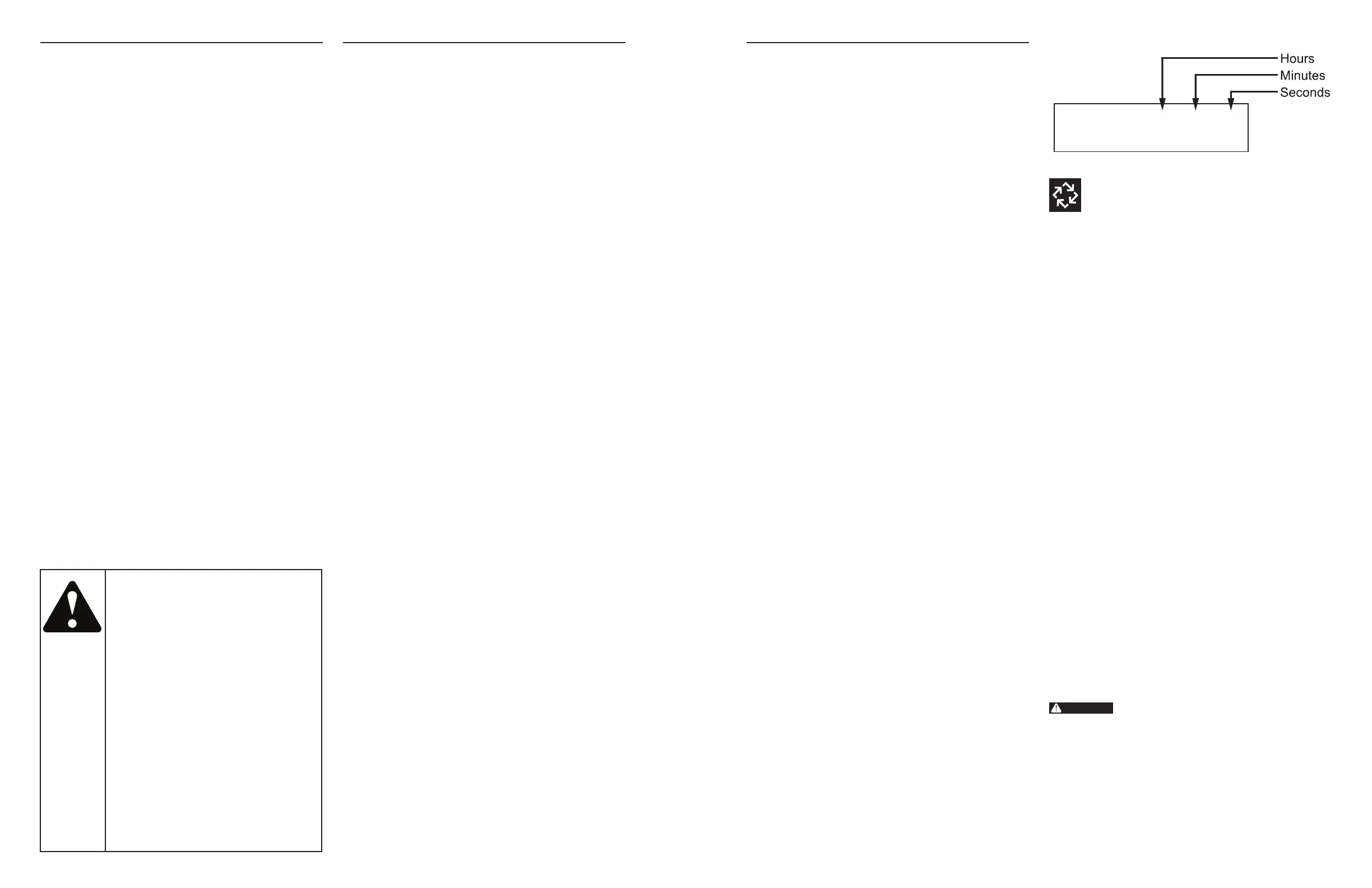
In the Regeneration Cycle step display, the timer shows
the current regeneration cycle number the valve is in, or
has reached, and the time remaining in that step. Once all
regeneration steps are complete the timer returns to In Service
and resumes normal operation.
CYCLE 1 00:00:00
BACK WASH
Example: 12 minutes remaining in Cycle 1 (Backwash)
Press the Extra Cycle button during a system
queued Regeneration Cycle to immediately
advance the valve to the next cycle step position
and resume normal step timing.
Flow Meter Equipped Timer
As treated water is used, the Volume Remaining display counts
down from the calculated system capacity to zero. When zero
is reached a Regeneration Cycle begins if no other units are in
regeneration.
Timer Operation During Programming
The timer enters the Program Mode in Standby or Service
Mode as long as it is not in regeneration. While in the Program
Mode the timer continues to operate normally monitoring
water usage. Timer programming is stored in memory
permanently.
Timer Operation During A Power Failure
All program settings are stored in permanent memory. Current
valve position, cycle step time elapsed, and time of day are all
stored during a power failure, and will be restored when power
is re-applied. Time is kept during a power failure, and time of
day is adjusted upon power up (as long as power is restored
within 12 hours).
NOTE: The time of day on the main display screen will flash
for 5 minutes when there has been a power outage.
The flashing of the time of day can be stopped by
pressing any button on the display.
Remote Lockout
The timer does not allow the unit/system to go into
Regeneration until the Regeneration Lockout Input signal to
the unit is cleared. This requires a contact closure to activate
the unit. The recommended gauge wire is 20 with a maximum
length of 500 feet. See P4 remote inputs in the wiring diagrams
in the service manual.
Regeneration Day Override Feature
If the Day Override option is turned on and the valve reaches
the set Regeneration Day Override value, the Regeneration
Cycle starts if no other unit is in Regeneration. If other units
are in regeneration, it is added to a regeneration queue. This
occurs regardless of the remaining volume available.
Transformer must be grounded and ground
wire must be terminated to the back plate
where grounding label is located before
installation.
IMPORTANT PLEASE READ:
• The information, specifications and illustrations in this manual
are based on the latest information available at the time of
printing. The manufacturer reserves the right to make changes
at any time without notice.
• This manual is intended as a guide for service of the controller
only. System installation requires information from a number of
suppliers not known at the time of manufacture. This product
should be installed by a plumbing professional.
• This unit is designed to be installed on potable water systems
only.
• This product must be installed in compliance with all state
and municipal plumbing and electrical codes. Permits may be
required at the time of installation.
• If daytime operating pressure exceeds 80 psi, nighttime
pressures may exceed pressure limits. A pressure reducing
valve must be installed.
• Do not install the unit where temperatures may drop below 32°F
(0°C) or above 110°F (43°C).
• Do not place the unit in direct sunlight. Black units will absorb
radiant heat increasing internal temperatures.
• Do not strike the controller or any of the components.
• Warranty of this product extends to manufacturing defects.
Misapplication of this product may result in failure to properly
condition water, or damage to product.
• A prefilter should be used on installations in which free solids
are present.
• Correct and constant voltage must be supplied to the controller
to maintain proper function.
TABLE OF CONTENTS
JOB SPECIFICATION SHEET .................................................... 2
TIMER OPERATION .................................................................. 3
SYSTEM DEFINITIONS ............................................................. 4
SYSTEM OPERATION IN SERVICE
(SYSTEM 14-DEMAND RECALL) .............................................. 5
FLOW IN A FOUR-UNIT SYTEM
(SYSTEM 14-DEMAND RECALL) .............................................. 6
TIMER DISPLAY FEATURES ..................................................... 6
TIMER DISPLAY - SCREEN EXAMPLES
(SYSTEM 4 THROUGH 6) .......................................................... 7
TRANSFORMER AND GROUND CONNECTIONS ..................... 7
NETWORK/COMMUNICATION CABLES AND CONNECTIONS 8
MASTER PROGRAMMING MODE FLOW CHART ...................... 8
USER PROGRAMMING MODE FLOW CHART ........................... 11
DIAGNOSTIC PROGRAMMING MODE FLOW CHART ............... 11
2750/2850/2900S UPPER & 2900S
LOWER POWERHEAD ASSEMBLY........................................... 13
3150/3900 UPPER & LOWER POWERHEAD ASSEMBLY ......... 15
METER ASSEMBLY PLASTIC ................................................... 17
1-INCH BRASS METER ASSEMBLY ......................................... 18
1-INCH STAINLESS STEEL METER ASSEMBLY ...................... 19
1-1/2 INCH BRASS METER ASSEMBLY ................................... 20
1-1/2 INCH STAINLESS STEEL METER ASSEMBLY ............... 21
2 INCH BRASS METER ASSEMBLY .......................................... 22
2 INCH STAINLESS STEEL METER ASSEMBLY ....................... 23
3 INCH BRASS METER ASSEMBLY .......................................... 24
3 INCH STAINLESS STEEL METER ASSEMBLY ....................... 25
SINGLE PISTON WIRING DIAGRAM ......................................... 26
DUAL PISTON WIRING DIAGRAM ............................................ 27
REMOTE TIMER WIRING DIAGRAM ......................................... 28
2750/2850 REMOTE TIMER WIRING DIAGRAM ....................... 29
2900 REMOTE TIMER WIRING DIAGRAM ................................ 30
3900 REMOTE TIMER WIRING DIAGRAM ................................ 31
3150 REMOTE METER WIRING DIAGRAM ............................... 32
TROUBLESHOOTING ................................................................ 33
JOB SPECIFICATION SHEET
Please Circle and/or Fill in the Appropriate Data for Future
Reference:
Programming Mode:
Feed Water Hardness: _________ Grains per Gallon or mg CaCO
3
/L
Regeneration Time: Delayed ______________AM/PM or Immediate
Regeneration Day Override: Off or Every __________________ Days
Master Programming:
System Type:
4 - Single Unit
5 - Parallel Unit
6 - Parallel Series Regen
7 - Twin Alternating
9 - Alternating
14 - Demand Recall
Valve Type: 2750 2850 2900s 3150 3900
System Size: 1 Valve 2 Valves 3 Valves 4 Valves
Valve Address: #1 #2 #3 #4
Regenerant Flow: Downflow or Upflow
Brine Draw First or Brine Fill First
Display Format: US Gallons or Liters
Unit Capacity: ________________________ Grains or grams CaCO
3
Capacity Safety Factor: Zero or ____________________________%
Trip Points (Gallons or M
3
):_____ Point 1 _____ Point 2 _____ Point 3
Trip Delays: _______ Delay 1 _______ Delay 2 _______ Delay 3
Regeneration Cycle Step #1: _ _ : _ _ : _ _
Regeneration Cycle Step #2: _ _ : _ _ : _ _
Regeneration Cycle Step #3: _ _ : _ _ : _ _
Regeneration Cycle Step #4: _ _ : _ _ : _ _
Regeneration Cycle Step #5: _ _ : _ _ : _ _
Timed Auxiliary Relay Output Window:
Off or Start Time _ _ : _ _ : _ _
End Time _ _ : _ _ : _ _
Chemical Pump Output Auxiliary Relay:
Off or Volume (Gallons or Liters) ______________________
Time _ _ : _ _ : _ _
Fleck Flow Meter Size:
Paddle: 1" 1.5" 2" 3"
Turbine: 1" 1.5"
Generic Flow Meter:
Maximum Flow Rate:
Add _ _ Gallons every _ _ Pulses
2 • Fleck 3200 NXT Fleck 3200 NXT • 3

 Loading...