TROUBLESHOOTING
Detected Errors
If a communication error is detected, an Error Screen will
alternate with the main (time of day) screen every few seconds.
• All units In Service remain in the In Service position.
• All units in Standby go to In Service.
• Any unit in Regeneration when the error occurs
completes Regeneration and goes to In Service.
• No units are allowed to start a Regeneration Cycle while
the error condition exists, unless they are manually forced
into Regeneration.
• When an error is corrected and the error no longer
displays (it may take several seconds for all of the units
in a system to stop displaying the error message), the
system returns to normal operation.
NOTE: During the error condition the control continues
to monitor the flow meter and update the volume
remaining. Once the error condition is corrected all
units return to the operating status they were in prior
to the error. Regeneration queue is rebuilt according
to the normal system operation. Or, if more than
one unit has been queued for regeneration, then the
queue is rebuilt according to which one communicates
first.
Message Displayed Cause For Error Correction
Flashing time Power outage. Program time by holding UP on Unit #1.
Detected Error = Matching Address
Two or more units programmed with the same valve address
number.
Program each unit with unique valve
address number in Master Programming.
Detected Error = Program Mismatch
Master program parameters do not match between two or
more controls.
Confirm Master Programming for each
unit.
Detected Error = No Message #1
No power to Control #1. Power Control #1.
Communication Cable to Valve Address #1 bad or missing. Connect or replace Communication Cable.
Detected Error = No Message #2
No power to Control #2. Power Control #2.
Communication Cable to Valve Address #2 bad or missing. Connect or replace Communication Cable.
Detected Error = No Message #3
No power to Control #3. Power Control #3.
Communication Cable to Valve Address #3 bad or missing. Connect or replace Communication Cable.
Detected Error = No Message #4
No power to Control #4. Power Control #4.
Communication Cable to Valve Address #4 bad or missing. Connect or replace Communication Cable.
Detected Error = E2 Reset Unit This message appears after a software reset.
Reprogram control using Master
Programming section.
Test Mode Circuit Board was not programmed at factory. Replace Circuit Board.
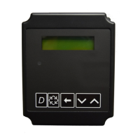
Black Squares on screen Bad Circuit Board. Replace Circuit Board.
INI on screen for more than 2
minutes
Circuit board not getting feedback from cycle switch.
Inspect Motor - should be rotating.
Connect wire harness to cycle switch.
Check Cycle Micro Switch.
CHG on screen for more than 2
minutes
Control programmed incorrectly as 2900 or 3900 valve type. Reprogram unit as Stager Valve type.
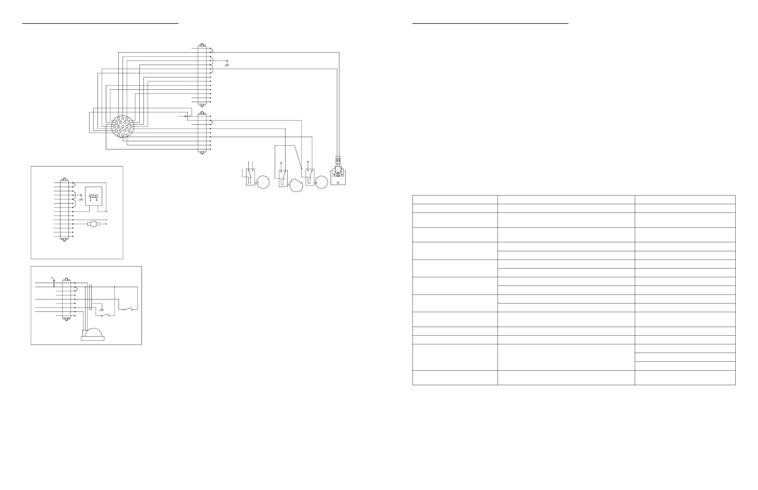
3150 REMOTE METER WIRING DIAGRAM
NOTE:
VALVE SHOWN IN SERVICE POSITION.
TB1 - HIGH VOLTAGE 14 POSITION TERMINAL BLOCK
TB2 - LOW VOLTAGE 9 POSITION TERMINAL BLOCK
IC1 - INTERLOCK CABLE RECEPTACLE
UDM - UPPER DRIVE MOTOR
LDM - LOWER DRIVE MOTOR
AUX - AUXILARY RELAY
HCAM - VALVE HOMING CAM
SCAM - VALVE STEP CAM
BVCAM - BRINE VALVE CAM
SW1 - VALVE HOMING SWITCH
SW2 - VALVE STEP SWITCH
M1
1
NEUTRAL
7
LDM
13
TYPICAL OUTPUT WIRING
1
3
EARTH GND
6
4
AUX
9
12
10
AUX
S1 - SOLENOID ON DURING REGENERATION 24VAC,0.25A MAX
M1 -OPTIONAL MOTOR/PUMP ON DURING REGENERATION
OR CPO DEVICE ON DURING SERVICE(N.O. OUTPUT)
2
5
UDM
8
11
TB1-GREY
LINE S1
HOT
NEUTRAL
250VAC/3A MAX. RESISTIVE
30VDC/3A MAX. RESISTIVE
P/N 19781
9
6
3
FLOW METER
+5 VDC
DC GROUND
7
8
4
1
5
2
(OPTIONAL)
SHIELD
TB2-ORANGE
(OPTIONAL)
(OPTIONAL)
SENSOR INPUT
METER INPUT
GREEN
RED
LOCKOUT INPUT
SENSOR SWITCH
LOCKOUT SWITCH
TYPICAL INPUT WIRING
13
14
15 16
17
18
19
1211
10
98
4
56
7
12
3
C
N.O.
N.C.
SW3
C
N.O.
N.C.
SW1
C
N.O.
N.C.
SW2
UDM
HCAM
SCAM
BVCAM
TAN
PINK
BLUE
HOME
P/N 19781
NOT USED
UDM
LINE
RED
BLACK
IC1
RED
GREY
METER
STEP
AUX
LDM
WHITE
GREEN
WHITE
+5 VDC
#BLACK
NOT USED
9
#WHITE/BLACK
6
3
DC GROUND#RED/BLACK
11
8
5
2KCALB
#ORANGE
8
#GREEN
SENSOR
7
2
#WHITE
4
1
TB2-ORANGE
13
01NWORB
12
AUX 9EGNARO
7
4WOLLEY
NOT USED 6
EARTH GND3NEERG
WHITENEUTRAL 1
1
TB1-GREY
#BLUE
LOCKOUT
5
#RED
# - DENOTES LOW VOLTAGE CABLE WIRE
NOT USED
BLACK
WHITE
BLACK
RED
NOT USED
WHITE
BLACK
32 • Fleck 3200 NXT Fleck 3200 NXT • 33
 Loading...