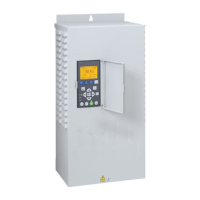
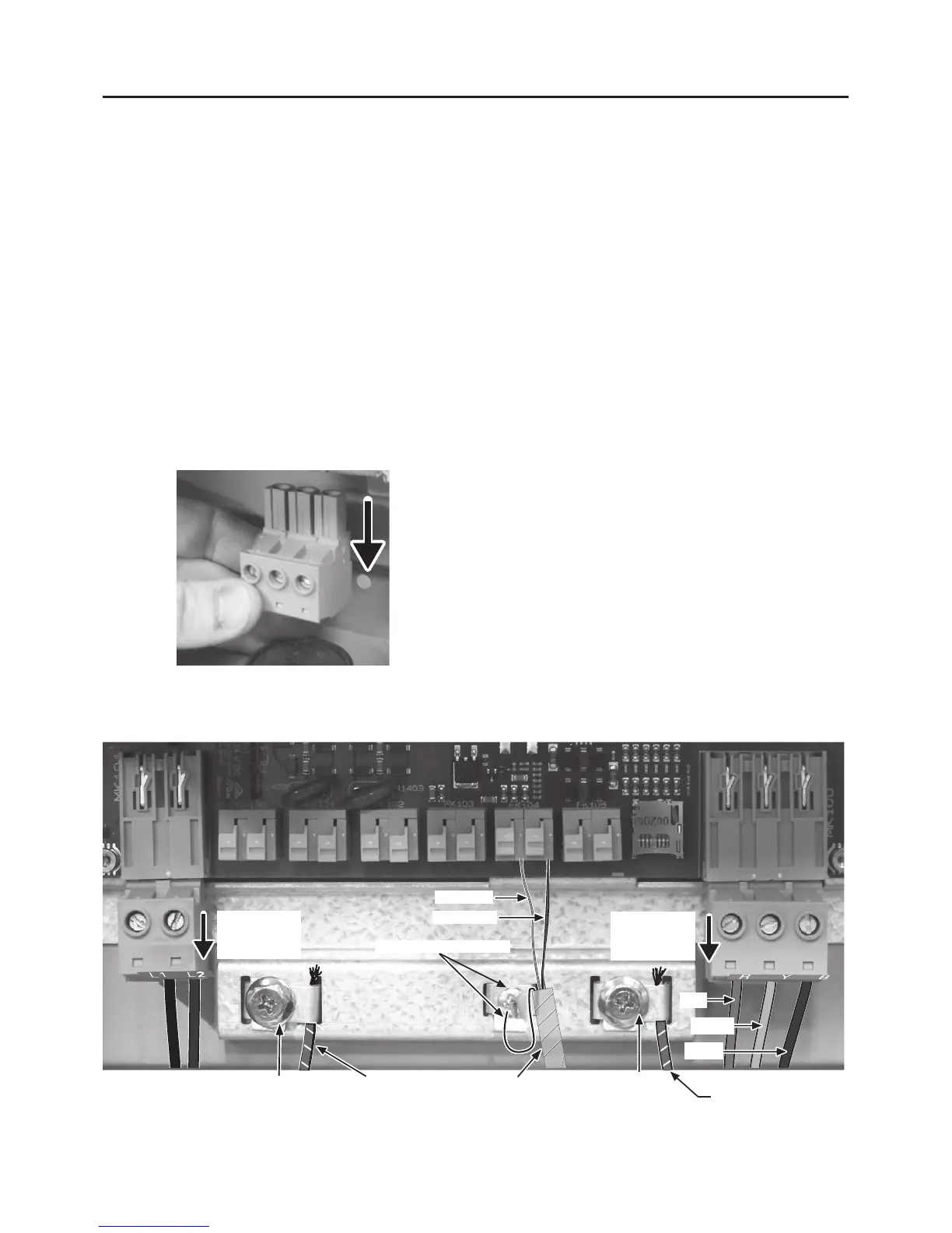
Motor Connections
Red to AI+
Black to AI–
Green Cable Shield/Screw
Terminal
Removable
(pull down)
Figure 9 - Basic Wiring Connections for Startup
Wiring
To allow for ease of wiring, the enclosure wiring
area is free of electronics other than the terminals.
Conduit holes and knockouts are located so
that the wire can be fed straight through to the
connectors, with minimal bending. The terminals
accept 6-14 AWG wire.
Installations that require larger wire gauge than
6AWG will require an external junction box. Run
6AWG wire from the Drive into the junction box,
then make external connections with wire nuts to
appropriately sized wire.
NOTICE For convenience in wiring, the input and
motor terminals unplug from the box. Pull them down
to remove them for ease of access, as shown in Figure
8.
Verify that the terminal connectors are completely
seated when you replace them. It is best practice
to connect all output wires (larger wire gauge) first,
then all input wires.
Pump Connections
If the PENTEK INTELLIDRIVE is used with above
ground motors (3-phase only) not rated for Variable
Frequency Drive use, maximize motor life by
limiting lead length to 25 ft. Refer to the pump
owner’s manual, the National Electrical Code, and
local codes for proper wire size.
The output of the Drive is single phase (2-wire or
3-wire) or 3-phase, depending on motor selection
during startup.
The output power terminals (motor wire
connections) are located on the lower right side of
the Drive and are labeled R (Red), Y (Yellow), and
B(Black).Toselectthewiresize,multiplythewire
length by 0.95 and then refer to the pump owner’s
manual, the Nation Electric Code, and local codes
for proper wire size.
NOTICE: Regardless of owner’s manual, wire
LENGTH may not exceed 1000 ft. (305 M).
NOTICE: 2-wire 1-phase connect to Y+B, not R+B.
Feed the motor cable through the 3/4” conduit hole
on the bottom right side and into the appropriate
terminals. If the wire is large enough to require a
larger conduit hole, remove the 1-1/4” knockout and
use the appropriate conduit connections. Attach the
motor ground wire to the grounding screw, located
on the grounding bar. Attach the motor power wires
to the terminals as shown in Figure 9.
NOTICE Drive does not sense motor temperature
and will not protect motor from over heating.
 Loading...