Installation 9
Pressure Tank Recommendations
Minimumtanksizeistwogallons.Useapre-
charged pressure tank with Drive, as shown in
Table3. The tank size must equal at least 20
percent of the pump’s rated flow in gallons per
minute(GPM),butcannotbelessthantwogallons
capacity.Forexample,apumpratedat7GPM
would require a tank of two gallons capacity or
larger.Apumpratedat50GPMwouldrequirea10
gallon tank or larger. Tanks larger than 10gallons
can be used, but may require adjustment of Wake
Delayparameter.
Table 3 - Control Pressure Set Point and Tank
Pre-Charge Pressure Values (PSI).
Pressure
Point
Setting
(PSI)
Precharge
Pressure
(PSI)
Pressure
Point
Setting
(PSI)
Precharge
Pressure
(PSI)
25 18 65 46
30 21 70 49
35 25 75 53
40 28 80 56
45 32 85 60
50 35 90 63
55 39 95 67
60
(Default)
42 –
NOTICE Set pressure tank’s pre-charge to 70
percent of the system operating pressure. When
using an external set point as well as an internal
set point, pre-charge tank to 70 percent of the
lower setpoint of the two. Some applications may
require a different percentage when determining
the setpoint.
Transducer Connections
A 0-100 PSI 4-20 mA transducer is provided with
Drive. Install the transducer downstream of tank,
as shown in Figure 1. Install transducer in a tee
in a straight section of pipe with at least 1 foot of
straight pipe on each side of the tee (i.e., all fittings
must be at least 1 foot away from transducer).
Feed transducer cable through the open 1/2”
conduit hole on bottom of the Drive enclosure.
As shown in Figure 9, connect the red wire of the
transducer cable to AI+, connect black wire to AI–,
and connect the cable shield to the metal cable
shield screw.
To connect the transducer wires:
1. Strip wire ½ inch
2. Push spring terminal up with finger or slotted
screwdriver
3. Insert wires from bottom
4. Release spring terminal
Input Power Connections
The input power terminals are located on the
lower left side and are marked L1 and L2 (see
Figure 9). There is a ground screw for the input
ground wire to the right of the connector (torque
to 10 inch lbs). Feed wire through the 3/4” conduit
hole on the bottom left side and into appropriate
terminals. If wire is large enough to require a larger
conduit hole, remove the 1-1/4” knockout and use
appropriate conduitconnections.
To determine the correct wire sizes for installation,
see Table 2.
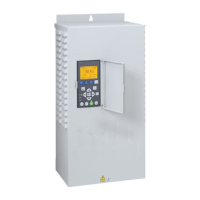
NOTICE The PENTEK
INTELLIDRIVE only accepts
230V single phase input power. If incoming power
does not match this, have a qualified electrician
alter supply voltage to 230V/1Ph before connecting
it to the Drive.
 Loading...