32
Section 5
Installation and Removal
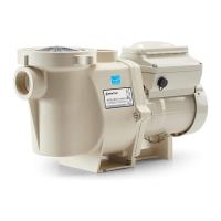
The following information describes how to install the IntelliFlo
®
pump.
Installing the IntelliFlo
®
Pump
Only a qualied service person should install the IntelliFlo
®
pump. Refer to “Important Warning And
Safety Instructions” on pages 4 to 6 for additional installation guidance and safety information.
IntelliFlo
®
Pump Kit Contents
IntelliFlo
®
VSD pump, eld wiring compartment cover, gasket, screws, grommet, and the
Installation and User’s Guide (this manual).
Location
1. Install the pump as close to the pool or spa as possible. To reduce friction loss and improve efciency,
use short and direct suction and piping returns.
2. Install a minimum of 1.52 meters (5 feet) from the inside wall of the pool and spa, or as required
by local regulations.
3. Install the pump a minimum of 0.9 meters (3 feet) from the heater outlet.
4. Do not install the pump more than 2.5 meters (8 feet) above the water level.
5. Install the pump in a sheltered well ventilated location protected from excessive moisture, (i.e., rain,
sprinklers, etc.).
6. For hot tubs and spas, do not install within an outer enclosure or beneath the skirt of a hot tub or
spa.
7. Install the pump with a rear clearance of at least 80 mm (3 inches) so that the motor can be removed
easily for maintenance and repair.
Piping
• For improved pool plumbing, it is recommended to use a larger pipe size. When installing the
inlet and outlet ttings (male adaptors), use thread sealant.
• Do not install 90° elbows directly into pump inlet or outlet. A valve, elbow or tee installed in
the suction line should be no closer to the front of the pump than ve times the suction line
pipe diameter (i.e., 50 mm (2 inch) pipe requires a 250 mm (10 inch) straight run in front of
the suction inlet of the pump). This will help the pump prime faster and last longer.
• Flooded suction systems should have gate valves installed on suction and discharge pipes for
maintenance, however, the suction gate valve should be no closer than ve times the suction
pipe diameter as described above.
Electrical
• A means for disconnection must be incorporated in the xed wiring in accordance with the
wiring rules.
• If the supply cord is damaged, it must be replaced to avoid a hazard.
• The pump is to be supplied through a residual current device (RCD) having a rated residual
operating current not exceeding 30mA. Use type A or B GFCI.
 Loading...