5
TAURUS™ VS Variable Speed Pump Installation and User’s Guide
Control with External Control and Digital Inputs
The user can run the Taurus™ VS Variable Speed Pump with automation external controls, allowing all four
programmed Speeds to be controlled remotely. The pump has a sealed connector that can be used with Pentair
External Control Wiring Kit (Pentair P/N 353129Z) to run the Speeds using digital input signals. When there is an
external low voltage signal present on the Speed Digital Input line, the pump will run the speed programmed for
that Digital Input. The supplied +5V signal is the recommended input used for external control and Speed Digital
Inputs.
Connecting to External Controls
Using the Supplied Low Voltage Signal for Digital Control
This pump provides a low voltage output signal that can be used to trigger its own Digital Inputs. This signal will
need to be switched via the External Control system to engage the speed that it is connected to as in Figure
4. This could be an automation relay or switch in another piece of equipment. This feature could be useful for
ensuring that the pump is running a certain program when a specific speed is needed to perform a task.
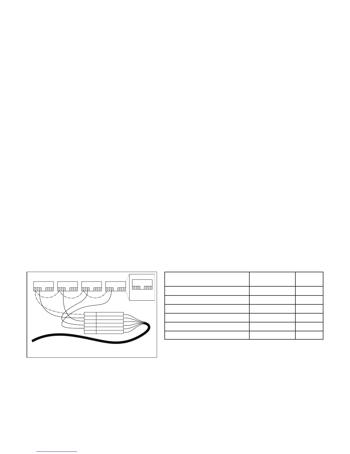
The wire included with the External Control Wiring Kit (Pentair P/N 353129Z) will need to be cut to length for the
installation. Do not leave excess wire around the installation, and the wire should be supported by something
rigid if conduit is not used. At one end of the cable is a custom molded, watertight connection that plugs into the
panel connection on the side of the drive. The opposite end has 6 wires that are defined by Table 1 below. When
using the +5V signal supplied by the drive, the speeds should be wired as shown in Figure 4.
When there is a low voltage signal present on the Speed Digital Input line the pump will run the speed that is
programmed for the speed that is being triggered. The +5V signal supplied via the (red) wire is the suggested
input for the Speed Digital Inputs. See Figure 4.
Note: Any relay can be associated to any Digital Input. Figure 4 shows one of many potential wiring options
available to the installer, allowing you to install External Controls in the way that best suits your needs.
Note: This +5V Signal (red wire) is output from the drive only, and should never be wired to another power
supply!
When a Speed Digital Input is triggered, the LED above the Speed button will begin to blink and the display will
toggle between the display parameter and “EC” indicating an External Control is running. The pump will run this
speed as long as the Digital Input trigger is present. This will override the schedule or any user inputs for Speed
selections via the keypad. The Display button is still functional along with the Start/Stop button. Once the Digital
Input trigger is removed from all of the Speed Digital Input wires, the pump will resume the programmed schedule.
RELAY 1 RELAY 2RELAY 3RELAY 4
RELAY
LINE 1
LOAD 1
LOAD 2
LINE 2
POWER RELAY (DPST)
RED
+5V OUTPUT FOR D.I. TRIGGER
GREEN SPEED 1 DIGITAL INPUT
YELLOWSPEED 2 DIGITAL INPUT
ORANGE SPEED 3 DIGITAL INPUT
BROWN
SPEED 4 DIGITAL INPUT
BLACK
GROUND
Figure 4:
External Control Kit Wiring Diagram
Denition Signal Range
Wire
Color
+5V Output for Digital Inputs 0 - 20mA Red
Speed 1 Digital Input 0, 5 - 30V AC/DC Green
Speed 2 Digital Input 0, 5 - 30V AC/DC Yellow
Speed 3 Digital Input 0, 5 - 30V AC/DC Orange
Quick Clean Digital Input 0, 5 - 30V AC/DC Brown
Common Ground 0V Black
Table 1:
Automation Control System Input Wiring Chart