70 SEBU8337
Maintenance Section
Engine Protective Devices - Check
i02568161
Engine Protectiv e D evi ces -
Check
Visual Inspection
Visually check the condition of all gauges, sensors
and wiring. Look for wiring and components that
are loose, bro
ken, or damaged. Damaged wiring
or components should be repaired or replaced
immediately.
Calibration Check
NOTICE
During testing, abnormal operating conditions must be
simulated.
The tests must be performed correctly in order to pre-
vent possibl
e damage to the engine.
Alarms and shutoffs must function properly. Alarms
provide time
ly warning to the operator. Shutoffs help
to prevent damage to the engine. It is impossible
to determine if the engine protective devices are
in good work
ing order during normal operation.
Malfunctions must be simulated in order to test the
engine protective devices. To prevent damage to the
engine, onl
y authorized service personnel or your
Perkins distributor should perform the tests.
Consult yo
ur Perkins distributor or refer to the Service
Manual for more information.
i02790456
Engine Speed/Timing Sensors
- C heck/Clean
/Calibrate
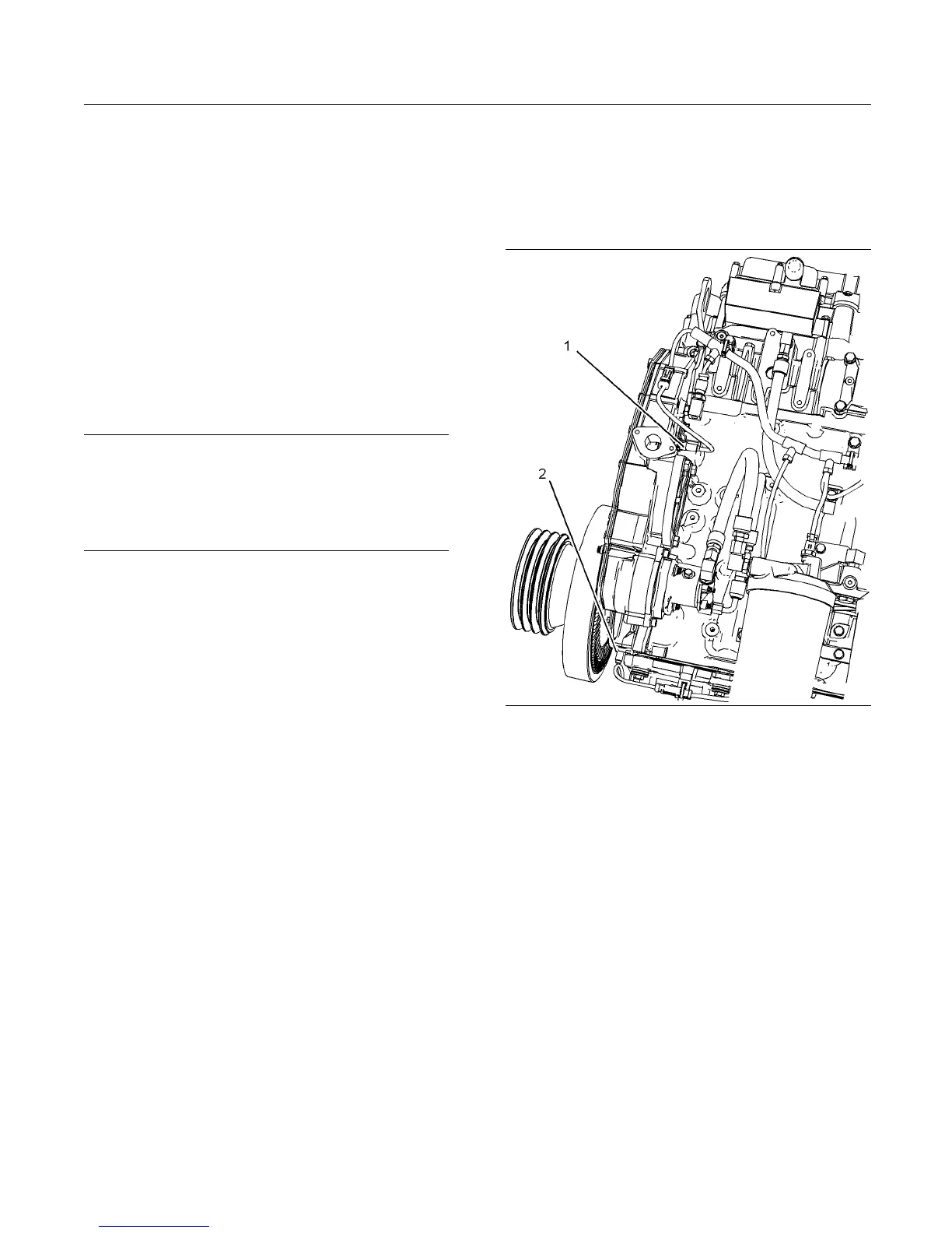
g01394162
Illustration 38
Left side view
(1) Secondary position sensor (Camshaft )
(2) Primary position sensor (Crankshaft)
1. Remove the sensors from the front housing.
Check the condition of the plastic end of the
sensors for wear and/or contaminants.
2. Clean the metal shavings and other debris from
the face of the sensors. Use the procedure in
the Service Manual in order to calibrate the
speed/timing sensors.
Refer to the Troubleshooting, “Calibration
Procedures” for more information on the speed/timing
sensors.