KENR9126 141
Troubleshooting Section
Test Step 4. Perform a P ull Test on Each
Wire Terminal Connection
g01802454
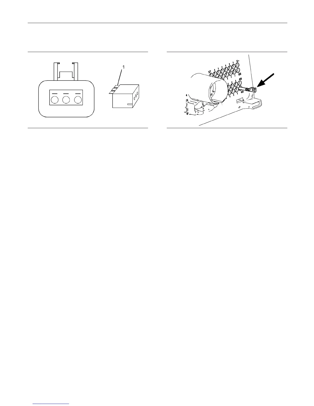
Illustration 42
A typical exam ple of the lock wedge.
(1) Lock w
edge
A. Ensure that the locking wedge for the connector
is insta
lled correctly. Terminals cannot be retained
inside the connector if the locking wedge is not
installed correctly.
B. Perform the 45 N (10 lb) pull test on each wire.
Each terminal and each connector should easily
withst
and45N(10lb)oftensionandeachwire
should remain in the connector body. This test
checks whether the wire was correctly crimped
in the t
erminal and whether the terminal was
correctly inserted into the connector.
Expec
ted Result:
Each terminal and each connector easily withstands
45 N (1
0 lb) of pull and each wire remains in the
connector body.
Resu
lts:
•
OK – All terminals pass the pull test. Proceed to
Test
Step 5.
•
Not OK – A wire has been pulled from a terminal
or a
terminal has been pulled from the connector.
Repair: Use the CH1 1155 Crimp Tool to replace
the
terminal. Replace damaged connectors, as
required.
Us
e the electronic service tool in order to clear all
logged diagnostic codes and then verify that the
repair eliminates the fault.
STOP.
Test Step 5. Check Individual Pin
Retention into the Socket
g01802455
Illustration 43
Diagram for testing pin r etention
A. Verify th
at the sockets provide good retention for
the pins. Insert a new pin into each socket one
atatimeinordertocheckforagoodgriponthe
pin by th
esocket.
Expected Result:
The sockets provide good retention for the new pin.
Result
s:
•
OK – The terminals are OK. Proceed to Test Step
6.
•
Not OK – Terminals are damaged.
Repair: Use the CH11155 Crimp Tool to replace
the damaged terminals. Verify that the repair
elimi
nates the problem.
Use the electronic service tool in order to clear all
logg
ed diagnostic codes and then verify that the
repair eliminates the fault.
STOP
.
Test Step 6. Check the Locking
Mechani sm of the Connectors
A. Ensure that the connectors lock correctly. After
locking the connectors, ensure that the two halves
ca
nnot be pulled apart.
B. Verify that the latch tab of the connector is
co
rrectly latched. Also verify that the latch tab of
the connector returns to the locked position.
E
xpected Result:
The connector is securely locked. The connector and
t
he locking mechanism is not cracked or broken.