KENR9126 137
Troubleshooting Section
g01802213
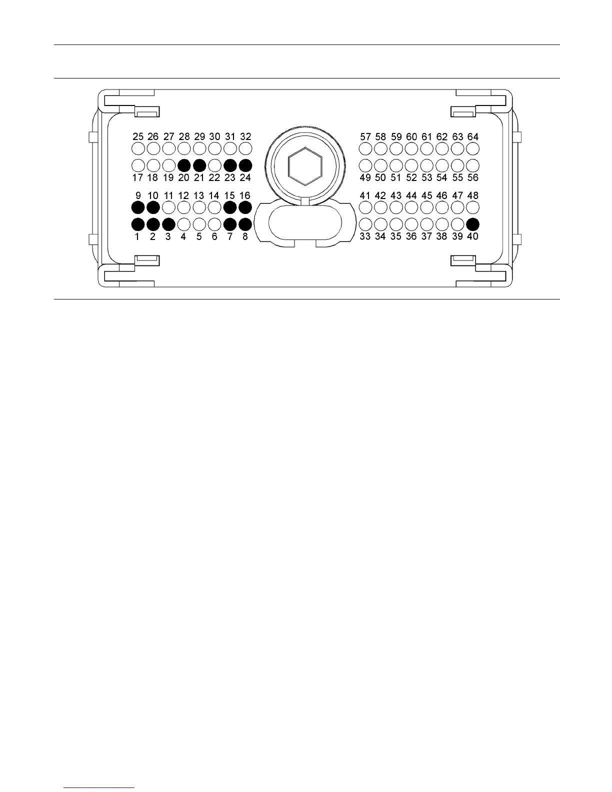
Illustration 37
Typical view of the pin locations on the P1 connector for the diagnostic and data link connectors
(1) Battery ground (GND)
(2) Battery ground (GND)
(3) Battery ground (GND)
(7) Battery +
(8) Battery +
(9) Battery ground (GND)
(10) Battery ground (GND)
(15) Battery +
(16) Battery +
(20) J1939 (CA N) +
(21) J1939 (CA N) -
(23) Data link +
(24) Data link -
(40) Keyswitch
A. Connect the battery wires from the bypass
harness of the electronic service tool to a different
battery that is not on the engine.
Expected Result:
The electronic service tool is operating correctly.
Results:
•
Yes
Repair: Refer to Troubleshooting, “Engine Wiring
Information”.
STOP.
•
No
Repair: Perform the followin g repair:
1. Make sure that the latest flash file for the
application is installed in the ECM. Refer to
Troubleshooting, “Flash Programming”.
2. Contact the Technical Help Desk.
Note: This consultation can greatly reduce the repair
time.
3. If the Technical Help Desk recommends the
use of a test ECM, install a test ECM. Refer to
Troubleshooting, “Replacing the ECM”.
4. Use the electronic service tool to recheck the
system for active diagnostic codes.
5. IfthefaultisresolvedwiththetestECM,
reconnect the suspect ECM.
6. If the fault returns with the suspect ECM,
replace the ECM.
7. Use the electronic service tool in order to clear
all logged diagnostic codes and then verify that
the repair eliminates the fault.
STOP.
i02493833
ECM Memory - Test
System Operation Description:
This procedure covers the following diagnostic codes:
•
0253-02 Personality Module erratic, intermittent,
or incorrect
Background Information
0253-02