KENR9126 167
Troubleshooting Section
g02193016
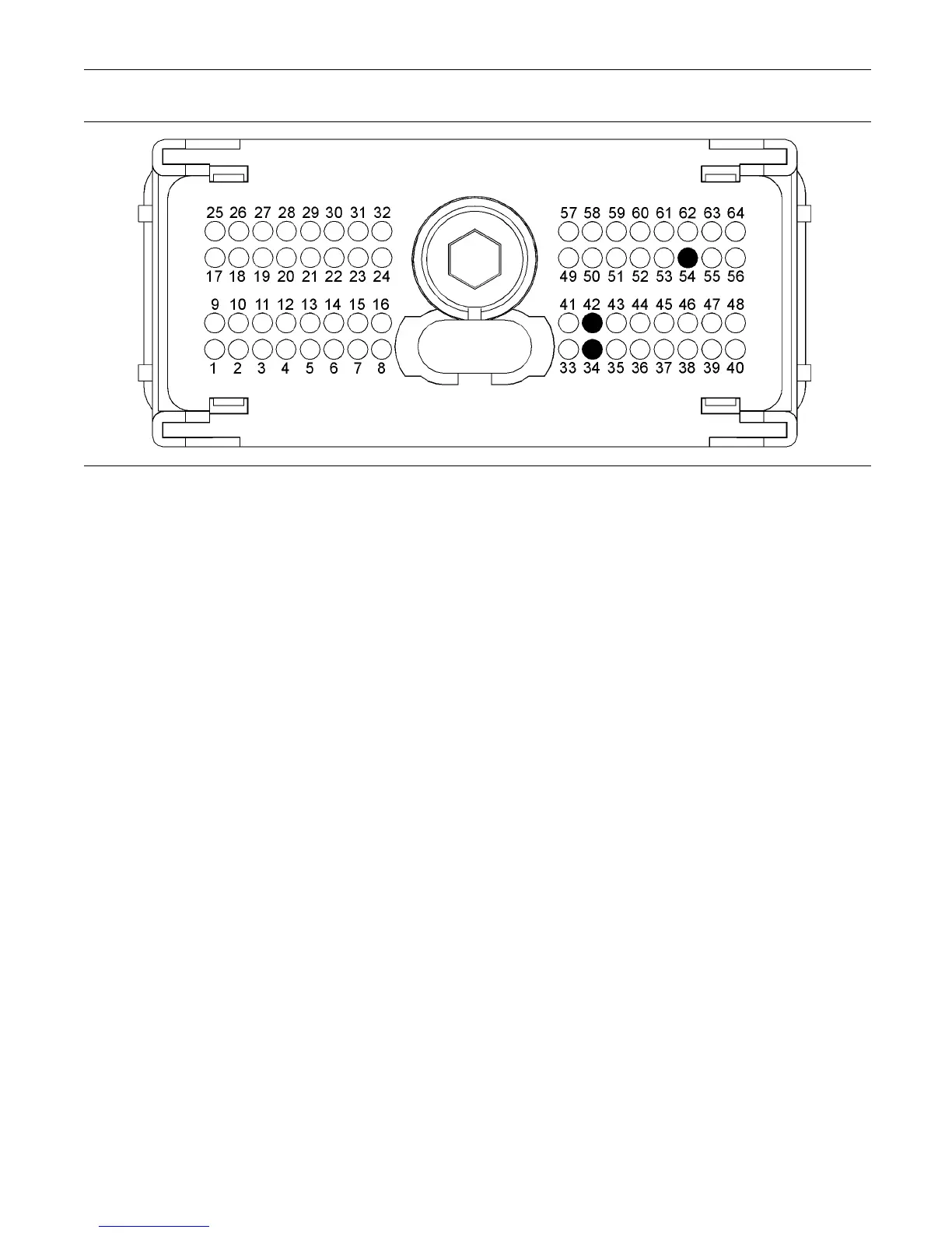
Illustration 64
A typical view of the P1 connector p in locations.
(34) Sensor return (42) Sensor +5 Volt supply (54) S ensor signal
Test Step 1. Inspect Electrical Connectors
And Wiring
A. Remove the electrical power from the ECM.
B. Thoroughly inspect the ECM engine harness
connector and the connector for the fuel
temperature sensor. Refer to Troubleshooting,
“Electrical Connectors - Inspect”.
C. Perform a 45 N (10 lb) pull test on each of the
wires that are associated with the fuel temperature
sensor.
D. Verify that the latch tab of the connector is
correctly latched.
E. Check the allen head screws for each ECM
connector for the proper torque. Refer to
Troubleshooting, “Electrical Connectors - Inspect”
for the correct torque values.
F. Check the harness for abrasions, for pinch points,
and for corrosion.
Expected Result:
All connectors, pins, and sockets are completely
coupled and/or inserted. The harness is free of
corrosion, of abrasion, and of pinch points.
Results:
•
OK – The connectors and wiring appear to be OK.
Proceed to Test Step 2.
•
Not OK – There is a fault in the connectors and/or
wiring.
Repair: Repair the connectors or wiring and/or
replace the connectors or wiring. Ensure that all of
the seals are correctly installed and ensure that the
connectors are completely coupled.
If necessary, perform the “Wiggle Test” on the
electronic service tool.
Use the electronic service tool in order to clear all
logged diagnostic codes and then verify that the
repair eliminates the fault.
STOP.
Test Step 2. C heck th e Supply Voltage at
the Sensor Connector
A. Remove the electrical power from th e ECM.
B. Disconnect the harness connector for the exhaust
gas temperature sensor.
C. Restore the electrical power to the ECM.
D. Measure the voltage between terminals A (+5
Volts DC) and B (Return) at the sensor connector
ontheengineharness.
E. Remove the electrical power from the ECM.
F. Reconnect the sensor.